3 Programming
3.1 Local Control Panel Operation
The frequency converter supports numerical local control
panel (NLCP), graphic local control panel (GLCP), and blind
cover. This chapter describes the operations with NLCP and
GLCP.
NOTICE
The frequency converter can also be programmed from
the MCT 10 Set-up Software on PC via RS485 communi-
cation port. This software can be ordered using code
number 130B1000 or downloaded from the Danfoss
website: www.danfoss.com/BusinessAreas/DrivesSolutions/
softwaredownload.
3.1.1 Numeric Local Control Panel (LCP)
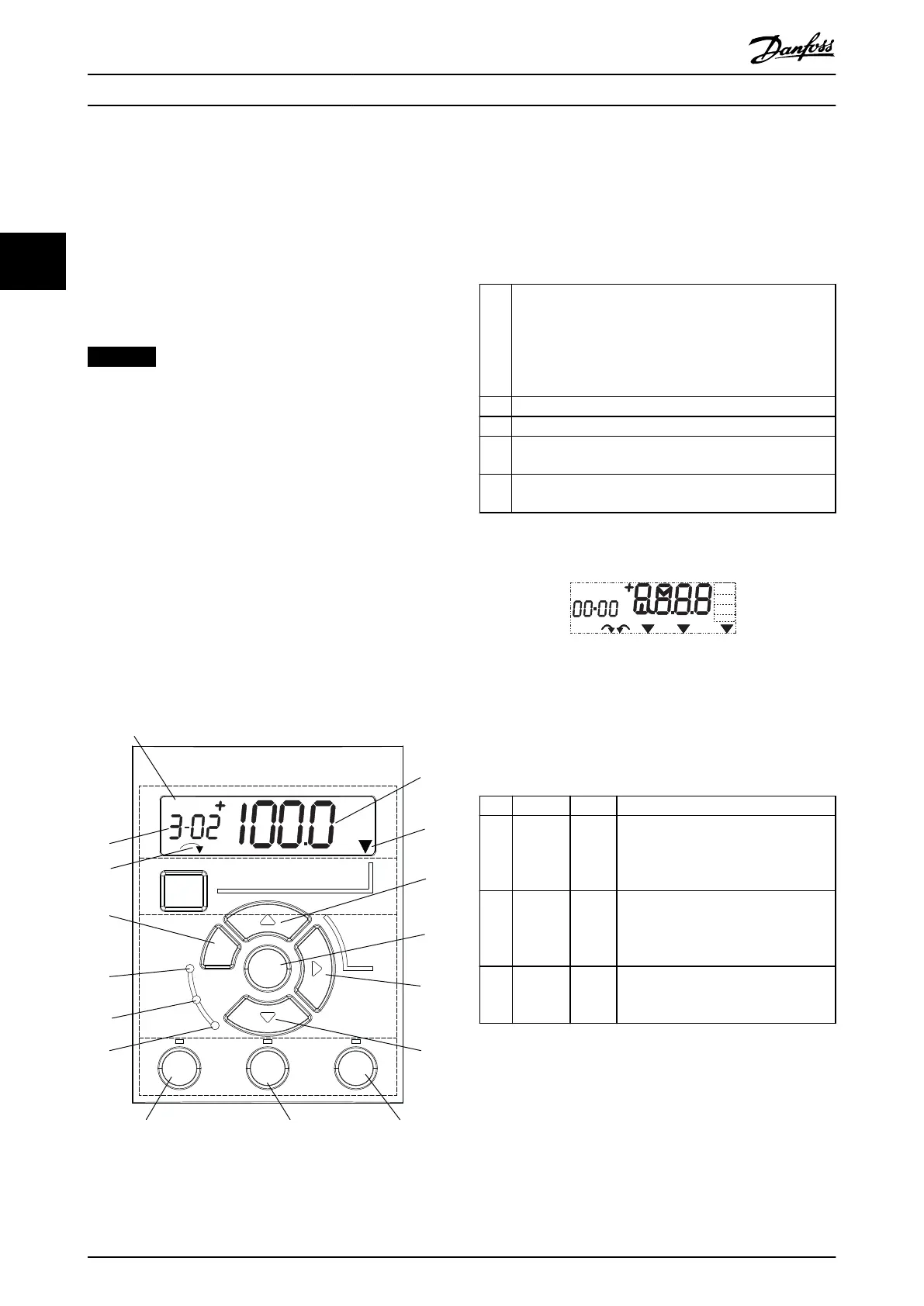
The numerical local control panel (NLCP) is divided into 4
functional sections.
A. Numeric display.
B. Menu key.
C. Navigation keys and indicator lights (LEDs).
D. Operation keys and indicator lights (LEDs).
130BC506.10
Setup 1
A
B
C
D
5
12
13 14 15
10
11
10
9
6
7
8
4
1
2
3
Menu
Status
Quick
Menu
Main
Menu
Hand
On
O
Reset
Auto
On
Back
OK
On
Warn
Alarm
Illustration 3.1 View of the NLCP
A. Numeric display
The LCD-display is back-lit with 1 numeric line. All data is
shown in the NLCP.
1 The set-up number shows the active set-up and the edit
set-up. If the same set-up acts as both active and edit set-
up, only that set-up number is shown (factory setting).
When active and edit set-up dier, both numbers are
shown in the display (for example set-up 12). The number
ashing indicates the edit set-up.
2 Parameter number.
3 Parameter value.
4 Motor direction is shown in the bottom left of the display.
A small arrow indicates the direction.
5 The triangle indicates whether the LCP is in Status, Quick
Menu, or Main Menu.
Table 3.1 Legend to Illustration 3.1, Section A
130BD135.10
Setup 1234
INDEX
AHP
VkW
srpm
Hz%
n2n1
n3
p5 p4
p3 p2 p1
Illustration 3.2 Display Information
B. Menu key
To select between Status, Quick Menu, or Main Menu,
press [Menu].
C. Indicator lights (LEDs) and navigation keys
Indicator Light Function
6 On Green ON turns on when the frequency
converter receives power from the
mains voltage, a DC bus terminal, or a
24 V external supply.
7 Warn Yellow When warning conditions are met, the
yellow WARN light turns on, and text
appears in the display area identifying
the problem.
8 Alarm Red A fault condition causes the red alarm
light to ash and an alarm text is
shown.
Table 3.2 Legend to Illustration 3.1, Indicator Lights (LEDs)
Programming
VLT
®
Midi Drive FC 280
12 Danfoss A/S © 12/2015 All rights reserved. MG07C102
33
 Loading...


