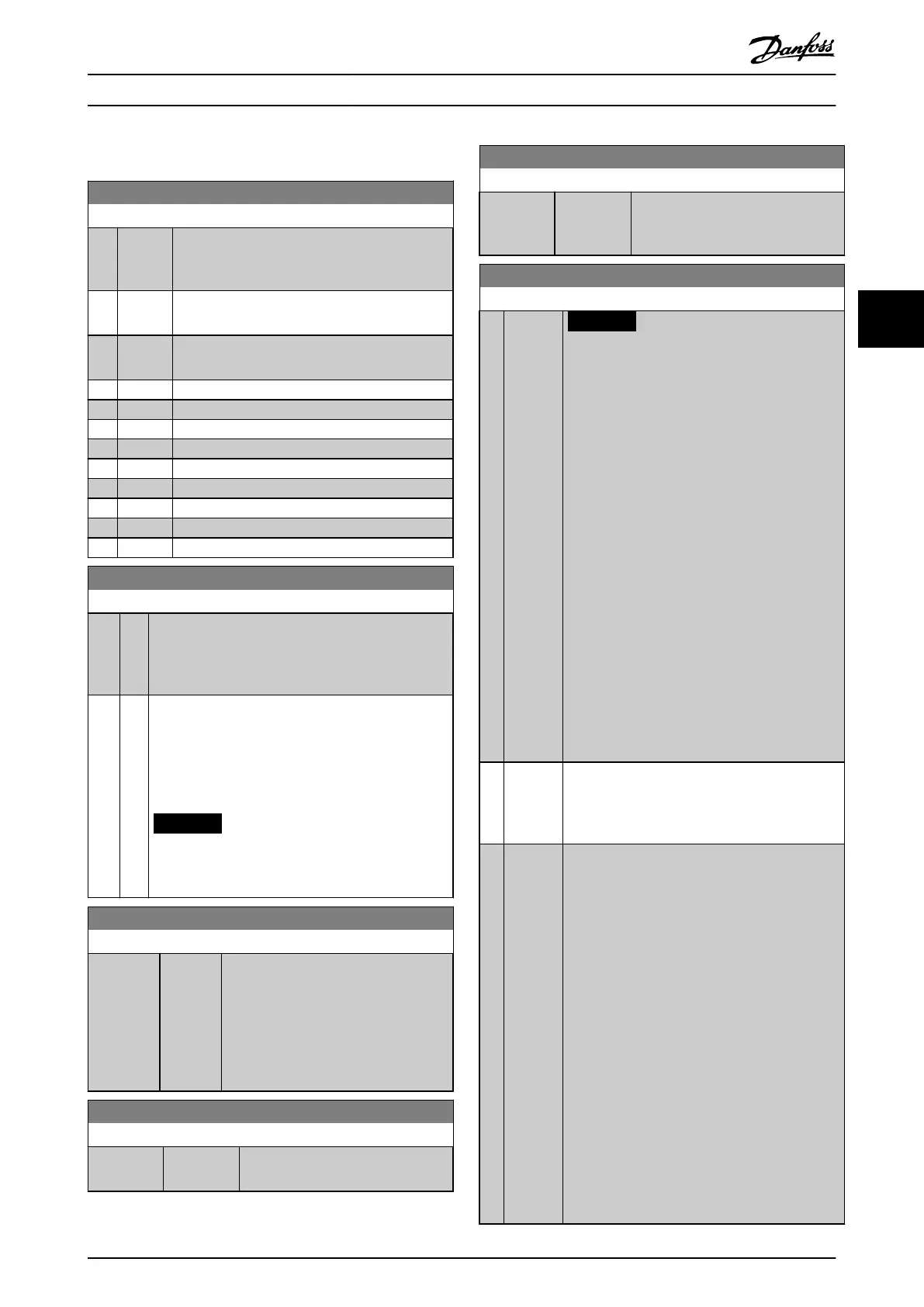
4.14 Parameters: 14-** Special Functions
14-01 Switching Frequency
Option: Function:
Select the inverter switching frequency. Changing
the switching frequency helps to reduce acoustic
noise from the motor.
[0] Ran3 3 kHz true random PWM (white noise
modulation).
[1] Ran5 5 kHz true random PWM (white noise
modulation).
[2] 2.0 kHz
[3] 3.0 kHz
[4] 4.0 kHz
[5] 5.0 kHz
[6] 6.0 kHz
[7] 8.0 kHz
[8] 10.0 kHz
[9] 12.0 kHz
[10] 16.0 kHz
14-03 Overmodulation
Option: Function:
[0] O To avoid torque ripple on the motor shaft, select [0]
O for no overmodulation of the output voltage. This
feature may be useful for applications such as grinding
machines.
[1] * On Select [1] On to enable the overmodulation function
for the output voltage. This is the right selection when
it is required that the output voltage is >95% of the
input voltage (typical when running oversynchro-
nously). The output voltage is increased according to
the degree of overmodulation.
NOTICE
Overmodulation leads to increased torque
ripple as harmonics are increased.
14-07 Dead Time Compensation Level
Range: Function:
Size
related*
[0 -
100 ]
Level of applied deadtime compensation
in percentage. A high level (>90%)
optimizes the dynamic motor response; a
level 50–90% is good for both motor-
torque-ripple minimization and the
motor dynamics. A 0-level turns the
deadtime compensation o.
14-08 Damping Gain Factor
Range: Function:
Size related* [0 - 100 %] Damping factor for DC-link voltage
compensation.
14-09 Dead Time Bias Current Level
Range: Function:
Size related* [0 - 100 %] Set a bias signal (in [%]) to add to
the current-sense signal for deadtime
compensation for some motors.
14-10 Mains Failure
Option: Function:
NOTICE
Parameter 14-10 Mains Failure cannot be
changed while motor is running.
Parameter 14-10 Mains Failure is typically used
where very short mains interruptions (voltage
dips) are present. At 100% load and a short
voltage interruption, the DC voltage on the main
capacitors drops quickly. For larger frequency
converters, it only takes a few milliseconds before
the DC level is down to about 373 V DC and the
IGBTs cut
o and lose control of the motor. When
mains is restored, and the IGBTs start again, the
output frequency, and voltage vector do not
correspond to the speed/frequency of the motor,
and the result is normally an overvoltage or
overcurrent, mostly resulting in a trip lock.
Parameter 14-10 Mains Failure can be programmed
to avoid this situation.
Select the function to which the frequency
converter must act when the threshold in
parameter 14-11 Mains Voltage at Mains Fault has
been reached.
[0]
*
No
function
The frequency converter does not compensate for
a mains interruption. The voltage on the DC-link
drops quickly, and the motor is lost within
milliseconds to seconds. Trip lock is the result.
[1] Ctrl.
ramp-
down
The frequency converter remains control of the
motor and does a controlled ramp-down from
parameter 14-11 Mains Voltage at Mains Fault level.
If parameter 2-10 Brake Function is [0] O or [2] AC
brake, the ramp follows the overvoltage ramping.
If parameter 2-10 Brake Function is [1] Resistor
Brake, the ramp follows the setting in
parameter 3-81 Quick Stop Ramp Time. This
selection is particularly useful in pump
applications, where the inertia is low and the
friction is high. When mains is restored, the
output frequency ramps the motor up to the
reference speed (if the mains interruption is
prolonged, the controlled ramp-down might take
the output frequency down to 0 RPM, and when
the mains is restored, the application is ramped
up from 0 RPM to the previous reference speed
via the normal ramp up). If the energy in the DC-
link disappears before the motor is ramped to 0,
the motor is coasted.
Parameter Descriptions Programming Guide
MG07C102 Danfoss A/S © 12/2015 All rights reserved. 91
4 4
 Loading...


