3-72 Ramp 4 Ramp Down Time
Range: Function:
motor, and such that the generated current
does not exceed the current limit set in
parameter 4-18 Current Limit. The value 0.00
corresponds to 0.01 s in speed mode. See
ramp-up time in parameter 3-71 Ramp 4
Ramp up Time.
Par . 3 − 72 =
t
dec
s xn
s
RPM
ref RPM
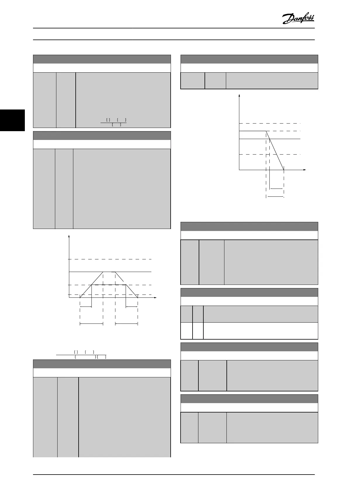
3-80 Jog Ramp Time
Range: Function:
Size
related*
[0.05
- 3600
s]
Enter the jog ramp time, which is the
acceleration/deceleration time between 0 RPM
and the rated motor frequency n
s
. Ensure that
the resulting output current required for the
given jog ramp time does not exceed the
current limit in parameter 4-18 Current Limit.
The jog ramp time starts when activating a
jog signal via the LCP, a selected digital
output, or the serial communication port.
When jog state is disabled, the normal
ramping times are valid.
130BD375.10
Time
P 3-80
Hz
P 4-14 Hz
high limit
P 1-25
Motor speed
Jog speed
P 3-19
P 3-80
Ramp up
(acc)
Ramp down
(dec)
t jog t jog
P 4-12 Hz
low limit
Illustration 4.6 Jog Ramp Time
Par . 3 − 80 =
t
jog
s xn
s
RPM
Δ jogspeed par . 3 − 19 RPM
3-81 Quick Stop Ramp Time
Range: Function:
Size
related*
[0.05 -
3600 s]
Enter the quick-stop ramp-down time,
which is the deceleration time from the
synchronous motor speed to 0 RPM. Ensure
that no resulting overvoltage occurs in the
inverter due to regenerative operation of
the motor required to achieve the given
ramp-down time. Ensure also that the
generated current required to achieve the
given ramp-down time does not exceed
the current limit (set in
parameter 4-18 Current Limit). Activate quick
3-81 Quick Stop Ramp Time
Range: Function:
stop with a signal on a selected digital
input, or via the serial communication port.
130BD376.10
Time
Hz
P 4-14 Hz
high limit
Reference
P 1-25
Motor speed
low limit
P 4-12 Hz
P 3-81
Qramp
Qstop
Illustration 4.7 Quick Stop Ramp Time
3-90 Step Size
Range: Function:
0.10 %
*
[0.01 -
200 %]
Enter the increment size required for
INCREASE/DECREASE, as a percentage of the
synchronous motor speed, n
s
. If INCREASE/
DECREASE is activated, the resulting
reference is increased/decreased by the
amount set in this parameter.
3-92 Power Restore
Option: Function:
[0] * O Resets the digital potentiometer reference to 0% after
power-up.
[1] On Restores the most recent digital potentiometer
reference at power-up.
3-93 Maximum Limit
Range: Function:
100 %* [-200 -
200 %]
Set the maximum permissible value for the
resulting reference. This is recommended if
the digital potentiometer is used for ne-
tuning of the resulting reference.
3-94 Minimum Limit
Range: Function:
-100 % [-200 -
200 %]
Set the minimum permissible value for the
resulting reference. This is recommended if
the digital potentiometer is used for ne-
tuning of the resulting reference.
Parameter Descriptions
VLT
®
Midi Drive FC 280
46 Danfoss A/S © 12/2015 All rights reserved. MG07C102
44
 Loading...


