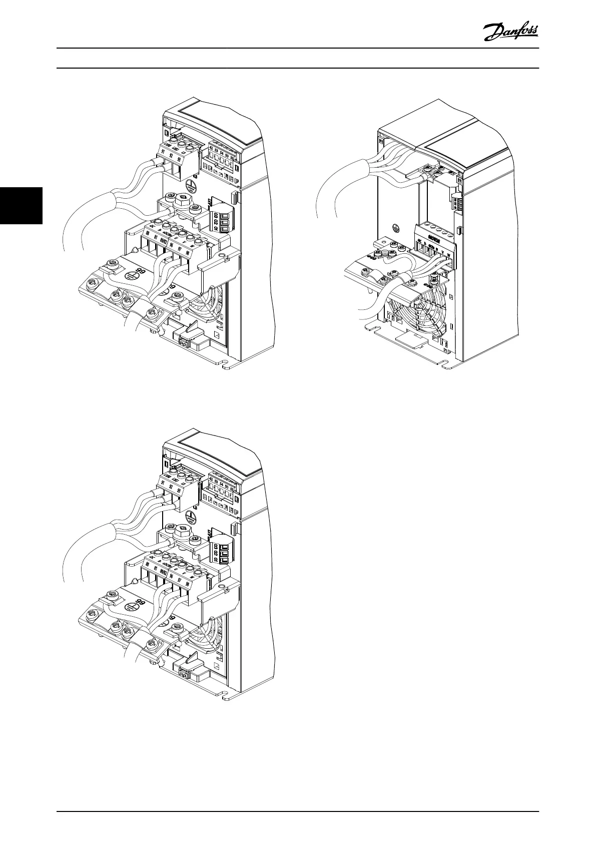
Illustration 4.6 Mains, Motor, and Grounding Connection for
Single-phase Units
Illustration 4.7 Mains, Motor, and Grounding Connection for 3-
phase Units (K1, K2, K3)
Illustration 4.8 Mains, Motor, and Grounding Connection for 3-
phase Units (K4, K5)
4.7
AC Mains Connection
•
Size the wiring based on the input current of the
frequency converter. For maximum wire sizes, see
chapter 9.1 Electrical Data.
•
Comply with local and national electrical codes
for cable sizes.
Procedure
1. Connect the AC input power cables to terminals
N and L for single-phase units (see
Illustration 4.6), or to terminals L1, L2, and L3 for
3-phase units (see Illustration 4.7).
2. Depending on the conguration of the
equipment, connect the input power to the
mains input terminals or the input disconnect.
3. Ground the cable in accordance with the
grounding instructions in chapter 4.3 Grounding.
4. When supplied from an isolated mains source (IT
mains or oating delta) or TT/TN-S mains with a
grounded leg (grounded delta), ensure that the
RFI lter screw is removed. Removing the RFI
screw prevents damage to the DC link and
reduces ground capacity currents in accordance
with IEC 61800-3 (see Illustration 9.2, the RFI
screw is on the side of the frequency converter).
Electrical Installation
VLT
®
Midi Drive FC 280
18 Danfoss A/S © 10/2017 All rights reserved. MG07A402
44
 Loading...


