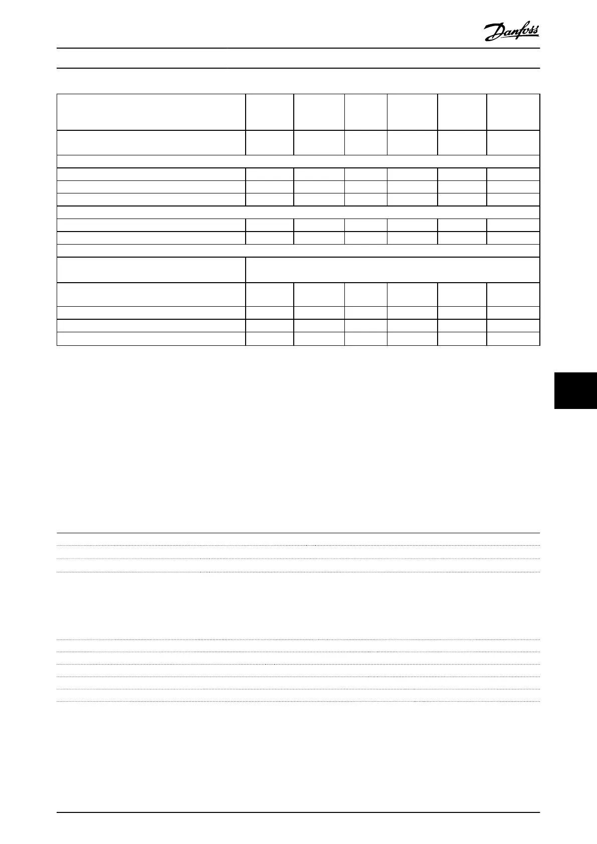
Frequency converter
typical shaft output [kW (hp)]
PK37
0.37
(0.5)
PK55
0.55
(0.75)
PK75
0.75
(1.0)
P1K1
1.1
(1.5)
P1K5
1.5
(2.0)
P2K2
2.2
(3.0)
Enclosure protection rating IP20 (IP21/Type 1 as
option)
K1 K1 K1 K1 K1 K2
Output current
Continuous (3x200–240 V) [A] 2.2 3.2 4.2 6 6.8 9.6
Intermittent (60 s overload) [A] 3.5 5.1 6.7 9.6 10.9 15.4
Continuous kVA (230 V AC) [kVA] 0.9 1.3 1.7 2.4 2.7 3.8
Maximum input current
Continuous (1x200–240 V) [A] 2.9 4.4 5.5 7.7 10.4 14.4
Intermittent (60 s overload) [A] 4.6 7.0 8.8 12.3 16.6 23.0
More specications
Maximum cable cross-section (mains and motor)
[mm
2
(AWG)]
4 (12)
Estimated power loss at rated maximum load [W]
1)
37.7 46.2 56.2 76.8 97.5 121.6
Weight enclosure protection rating IP20 [kg (lb)] 2.3 (5.1) 2.3 (5.1) 2.3 (5.1) 2.3 (5.1) 2.3 (5.1) 2.5 (5.5)
Weight enclosure protection rating IP21 [kg (lb)] 4.0 (8.8) 4.0 (8.8) 4.0 (8.8) 4.0 (8.8) 4.0 (8.8) 5.5 (12.1)
Eciency [%]
2)
94.4 95.1 95.1 95.3 95.0 95.4
Table 9.4 Mains Supply 1x200–240 V AC
1) The typical power loss is at nominal load conditions and expected to be within
±
15% (tolerance relates to variety in voltage and cable
conditions).
Values are based on a typical motor eciency (IE2/IE3 border line). Motors with lower eciency add to the power loss in the frequency converter,
and motors with high eciency reduce power loss.
Applies to dimensioning of frequency converter cooling. If the switching frequency is higher than the default setting, the power losses sometimes
rise. LCP and typical control card power consumptions are included. Further options and customer load sometimes add up to 30 W to the losses
(though typically only 4 W extra for a fully loaded control card or eldbus).
For power loss data according to EN 50598-2, refer to www.danfoss.com/vltenergyeciency.
2) Measured using 50 m (164 ft) shielded motor cables at rated load and rated frequency. For energy eciency class, see chapter 9.4 Ambient
Conditions. For part load losses, see www.danfoss.com/vltenergyeciency.
9.2
Mains Supply
Mains supply (L1/N, L2/L, L3)
Supply terminals (L1/N, L2/L, L3)
Supply voltage 380–480 V: -15% (-25%)
1)
to +10%
Supply voltage 200–240 V: -15% (-25%)
1)
to +10%
1) The frequency converter can run at -25% input voltage with reduced performance. The maximum output power of the
frequency converter is 75% if input voltage is -25%, and 85% if input voltage is -15%.
Full torque cannot be expected at mains voltage lower than 10% below the lowest rated supply voltage of the frequency
converter.
Supply frequency 50/60 Hz ±5%
Maximum imbalance temporary between mains phases 3.0% of rated supply voltage
True power factor (λ) ≥0.9 nominal at rated load
Displacement power factor (cos ϕ) Near unity (>0.98)
Switching on input supply (L1/N, L2/L, L3) (power-ups) ≤7.5 kW (10 hp) Maximum 2 times/minute
Switching on input supply (L1/N, L2/L, L3) (power-ups) 11–22 kW (15–30 hp) Maximum 1 time/minute
Specications Operating Guide
MG07A402 Danfoss A/S © 10/2017 All rights reserved. 55
9 9
 Loading...


