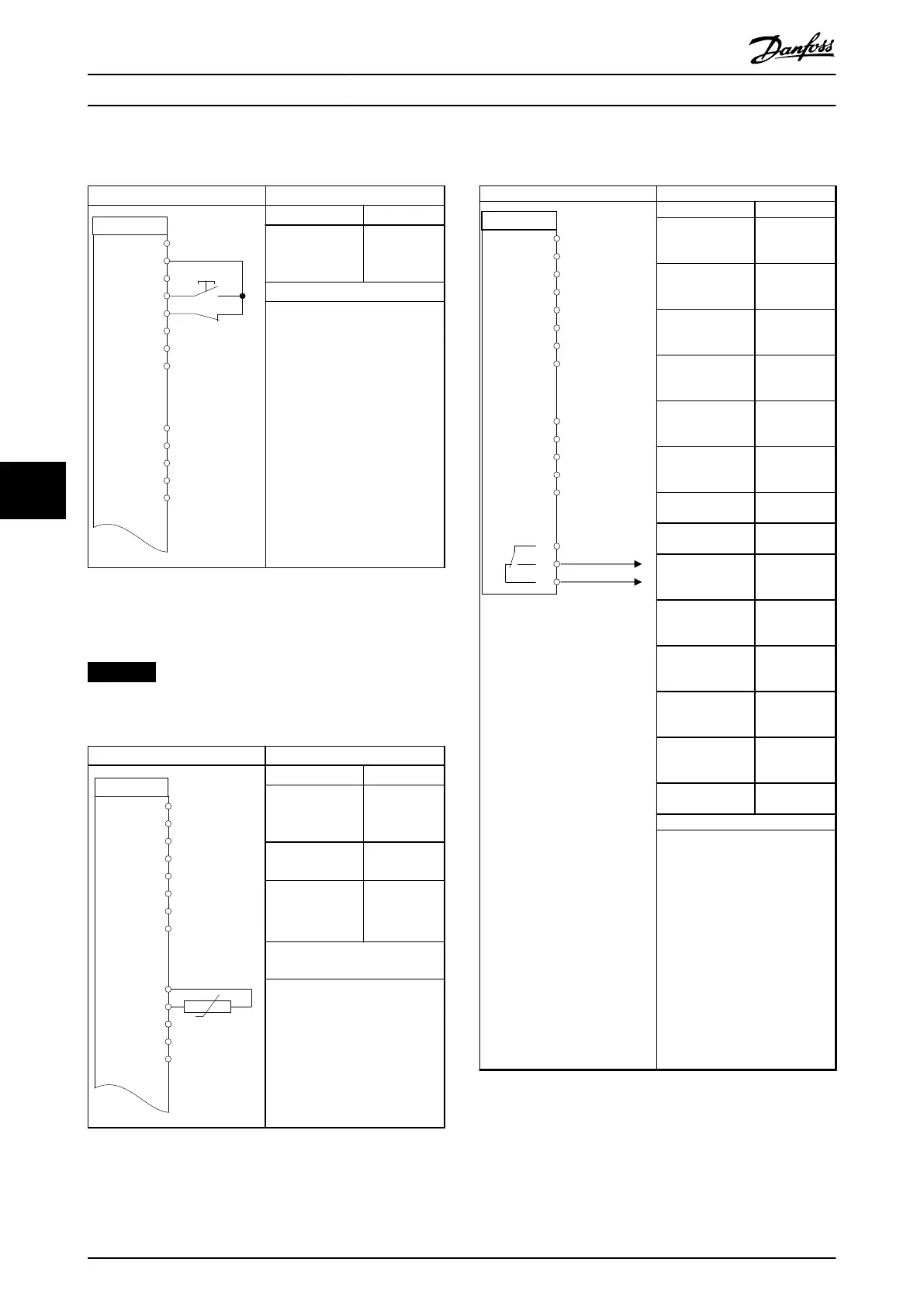
7.2.4 External Alarm Reset
Parameters
130BF099.10
FC
+24 V
D IN
D IN
D IN
D IN
D IN
D IN
+10 V
A IN
A IN
COM
A OUT
12
13
18
19
27
29
32
33
50
53
54
55
42
+24 V
Function Setting
Parameter 5-11 T
erminal 19
Digital Input
[1] Reset
* = Default value
Notes/comments:
Table 7.7 External Alarm Reset
7.2.5 Motor Thermistor
NOTICE
To meet PELV insulation requirements, use reinforced or
double insulation on the thermistors.
Parameters
130BE210.11
+24 V
D IN
D IN
D IN
D IN
D IN
+10 V
A IN
A IN
COM
A OUT
12
13
18
19
27
29
32
33
50
53
54
55
42
FC
D IN
+24 V
Function Setting
Parameter 1-90
Motor Thermal
Protection
[2] Thermistor
trip
Parameter 1-93 T
hermistor Source
[1] Analog
input 53
Parameter 6-19 T
erminal 53 mode
[1] Voltage
* = Default value
Notes/comments:
If only a warning is needed, set
parameter 1-90 Motor Thermal
Protection to [1] Thermistor
warning.
Table 7.8 Motor Thermistor
7.2.6 SLC
Parameters
FC
+24 V
D IN
D IN
D IN
D IN
D IN
D IN
+10 V
A IN
A IN
COM
A OUT
R1
12
13
18
19
27
29
32
33
50
53
54
55
42
01
02
03
130BE211.11
+24 V
Function Setting
Parameter 4-30
Motor Feedback
Loss Function
[1] Warning
Parameter 4-31
Motor Feedback
Speed Error
50
Parameter 4-32
Motor Feedback
Loss Timeout
5 s
Parameter 7-00 S
peed PID
Feedback Source
[1] 24 V
encoder
Parameter 5-70 T
erm 32/33 Pulses
Per Revolution
1024*
Parameter 13-00
SL Controller
Mode
[1] On
Parameter 13-01
Start Event
[19] Warning
Parameter 13-02
Stop Event
[44] Reset key
Parameter 13-10
Comparator
Operand
[21] Warning
no.
Parameter 13-11
Comparator
Operator
*[1] ≈
Parameter 13-12
Comparator
Value
61
Parameter 13-51
SL Controller
Event
[22]
Comparator 0
Parameter 13-52
SL Controller
Action
[32] Set
digital out A
low
Parameter 5-40 F
unction Relay
[80] SL digital
output A
* = Default value
Notes/comments:
If the limit in the feedback
monitor is exceeded, warning
61, feedback monitor is issued.
The SLC monitors warning 61,
feedback monitor. If warning 61,
feedback monitor becomes true,
relay 1 is triggered.
External equipment could
indicate that service is required.
If the feedback error goes
below the limit again within
5 s, the frequency converter
continues, and the warning
disappears. Relay 1 persists
until
[O/Reset] is pressed.
Table 7.9 Using SLC to Set a Relay
Application Examples
VLT
®
Midi Drive FC 280
44 Danfoss A/S © 10/2017 All rights reserved. MG07A402
77
 Loading...


