8.4 List of Warnings and Alarms
8.4.1 Warning and Alarm Code List
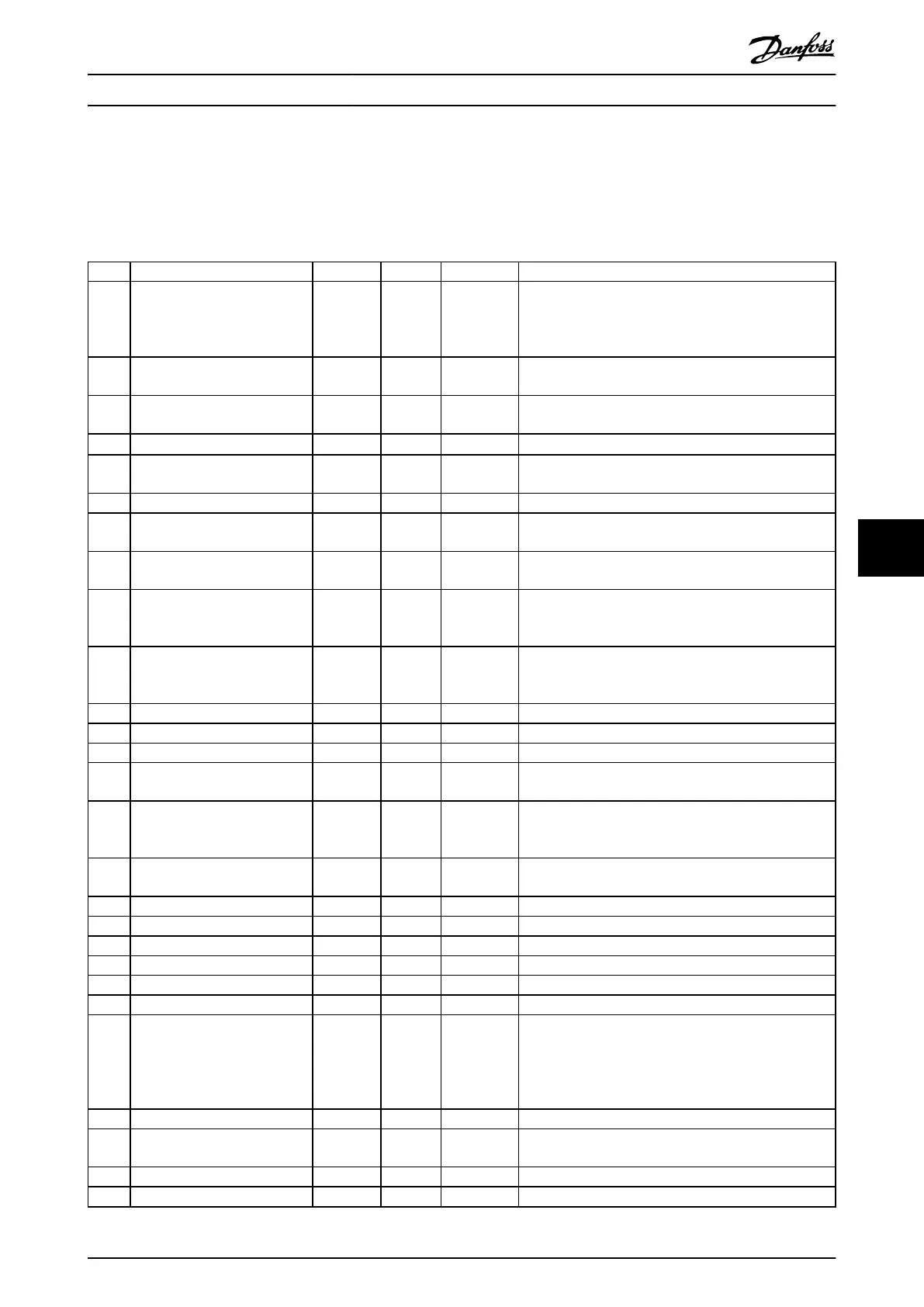
An (X) marked in Table 8.1 indicates that the warning or alarm has occurred.
No. Description Warning Alarm Trip lock Cause
2 Live zero error X X –
The signal on terminal 53 or 54 is less than 50% of the
value set in parameter 6-10 Terminal 53 Low Voltage,
parameter 6-20 Terminal 54 Low Voltage, and
parameter 6-22 Terminal 54 Low Current.
3 No motor X – –
No motor has been connected to the output of the
frequency converter.
4
Mains phase loss
1)
X X X
Missing phase on the supply side, or the voltage
imbalance is too high. Check the supply voltage.
7
DC overvoltage
1)
X X –
DC-link voltage exceeds limit.
8
DC undervoltage
1)
X X –
DC-link voltage drops below the voltage warning low
limit.
9 Inverter overloaded X X – More than 100% load for too long.
10 Motor ETR overtemperature X X –
Motor is too hot due to more than 100% load for too
long.
11
Motor thermistor overtem-
perature
X X –
Thermistor or thermistor connection is disconnected, or
the motor is too hot.
12 Torque limit X X –
Torque exceeds the value set in either
parameter 4-16 Torque Limit Motor Mode or
parameter 4-17 Torque Limit Generator Mode.
13 Overcurrent X X X
Inverter peak current limit is exceeded. If this alarm
occurs on power-up, check whether power cables are
mistakenly connected to the motor terminals.
14 Ground fault – X X Discharge from output phases to ground.
16 Short circuit – X X Short circuit in motor or on motor terminals.
17 Control word timeout X X – No communication to frequency converter.
25 Brake resistor short-circuited – X X
Brake resistor is short-circuited, thus the brake function is
disconnected.
26 Brake overload X X –
The power transmitted to the brake resistor over the last
120 s exceeds the limit. Possible corrections: Decrease
brake energy via lower speed or longer ramp time.
27
Brake IGBT/brake chopper short-
circuited
– X X
Brake transistor is short-circuited, thus the brake function
is disconnected.
28 Brake check – X – Brake resistor is not connected/working.
30 U phase loss – X X Motor phase U is missing. Check the phase.
31 V phase loss – X X Motor phase V is missing. Check the phase.
32 W phase loss – X X Motor phase W is missing. Check the phase.
34 Fieldbus fault X X – PROFIBUS communication issues have occurred.
35 Option fault – X – Fieldbus detects internal faults.
36 Mains failure X X –
This warning/alarm is only active if the supply voltage to
the frequency converter is less than the value set in
parameter 14-11 Mains Fault Voltage Level, and
parameter 14-10 Mains Failure is NOT set to [0] No
Function.
38 Internal fault – X X Contact the local Danfoss supplier.
40 Overload T27 X – –
Check the load connected to terminal 27 or remove
short-circuit connection.
46 Gate drive voltage fault – X X –
47 24 V supply low X X X 24 V DC may be overloaded.
Maintenance, Diagnostics, a... Operating Guide
MG07A402 Danfoss A/S © 10/2017 All rights reserved. 47
8 8
 Loading...


