4. Remove the 24 V supply for terminal 38 and
verify that the LCP shows alarm 188, STO Function
Fault if the LCP is mounted. If the LCP is not
mounted, verify that alarm 188, STO Function Fault
is logged in parameter 15-30 Alarm Log: Error
Code.
5. Reapply 24 V supply to terminal 38 and verify
that resetting the alarm is successful.
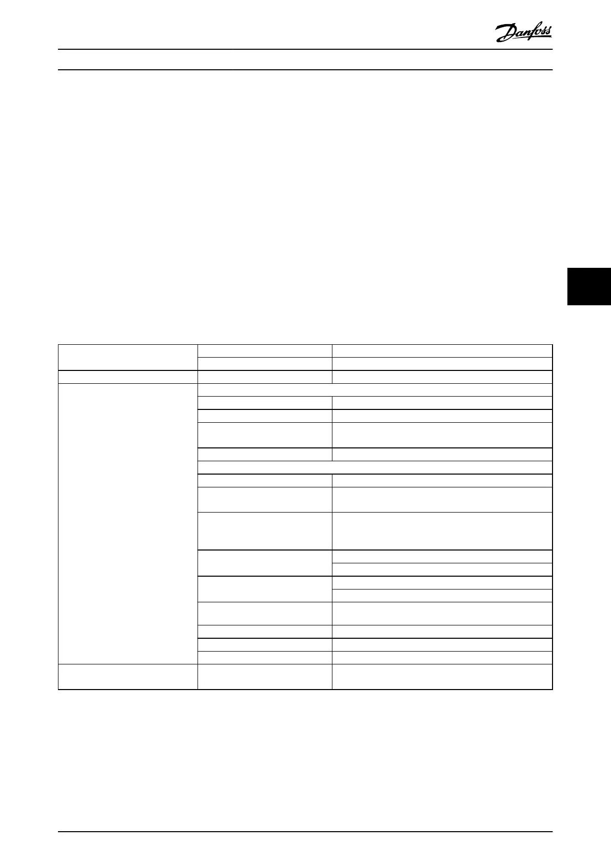
6.5 STO Technical Data
The Failure Modes, Eects, and Diagnostic Analysis (FMEDA) is performed based on the following assumptions:
•
VLT
®
Midi Drive FC 280 takes 10% of the total failure budget for an SIL2 safety loop.
•
Failure rates are based on the Siemens SN29500 database.
•
Failure rates are constant; wear-out mechanisms are not included.
•
For each channel, the safety-related components are considered to be of type A with a hardware fault tolerance
of 0.
•
The stress levels are average for an industrial environment and the working temperature of components is up
to 85 °C (185 °F).
•
A safe error (for example output in safe state) is repaired within 8 hours.
•
No torque output is the safe state.
Safety standards
Safety of Machinery ISO 13849-1, IEC 62061
Functional Safety IEC 61508
Safety function Safe Torque O IEC 61800-5-2
Safety performance
ISO 13849-1
Category Cat. 3
Diagnostic coverage (DC) 60% (Low)
Mean time to dangerous failure
(MTTFd)
2400 years (High)
Performance level PL d
IEC 61508/IEC 61800-5-2/IEC 62061
Safety Integrity Level SIL2
Probability of dangerous failure per
hour (PFH) (high demand mode)
7.54E-9 (1/h)
Probability of dangerous failure on
demand (PFD
avg
for PTI = 20 years)
(low demand mode)
6.05E-4
Safe failure fraction (SFF)
For dual-channel parts: >84%
For single-channel parts: >99%
Hardware fault tolerance (HFT)
For dual-channel parts: HFT = 1
For single-channel parts: HFT = 0
Proof test interval
2)
20 years
Common cause failure (CCF) β = 5%; β
D
= 5%
Diagnostic test interval (DTI) 160 ms
Systematic capability SC 2
Reaction time
1)
Input to output response time Enclosure sizes K1–K3: Maximum 50 ms
Enclosure sizes K4 and K5: Maximum 30 ms
Table 6.3 Technical Data for STO
1) Reaction time is the amount of time from an input signal condition triggers the STO until the torque is o on the motor.
2) For proof test procedure, refer to chapter 6.4 Maintenance and Service for STO.
Safe Torque O (STO) Operating Guide
MG07A402 Danfoss A/S © 10/2017 All rights reserved. 41
6
6
 Loading...


