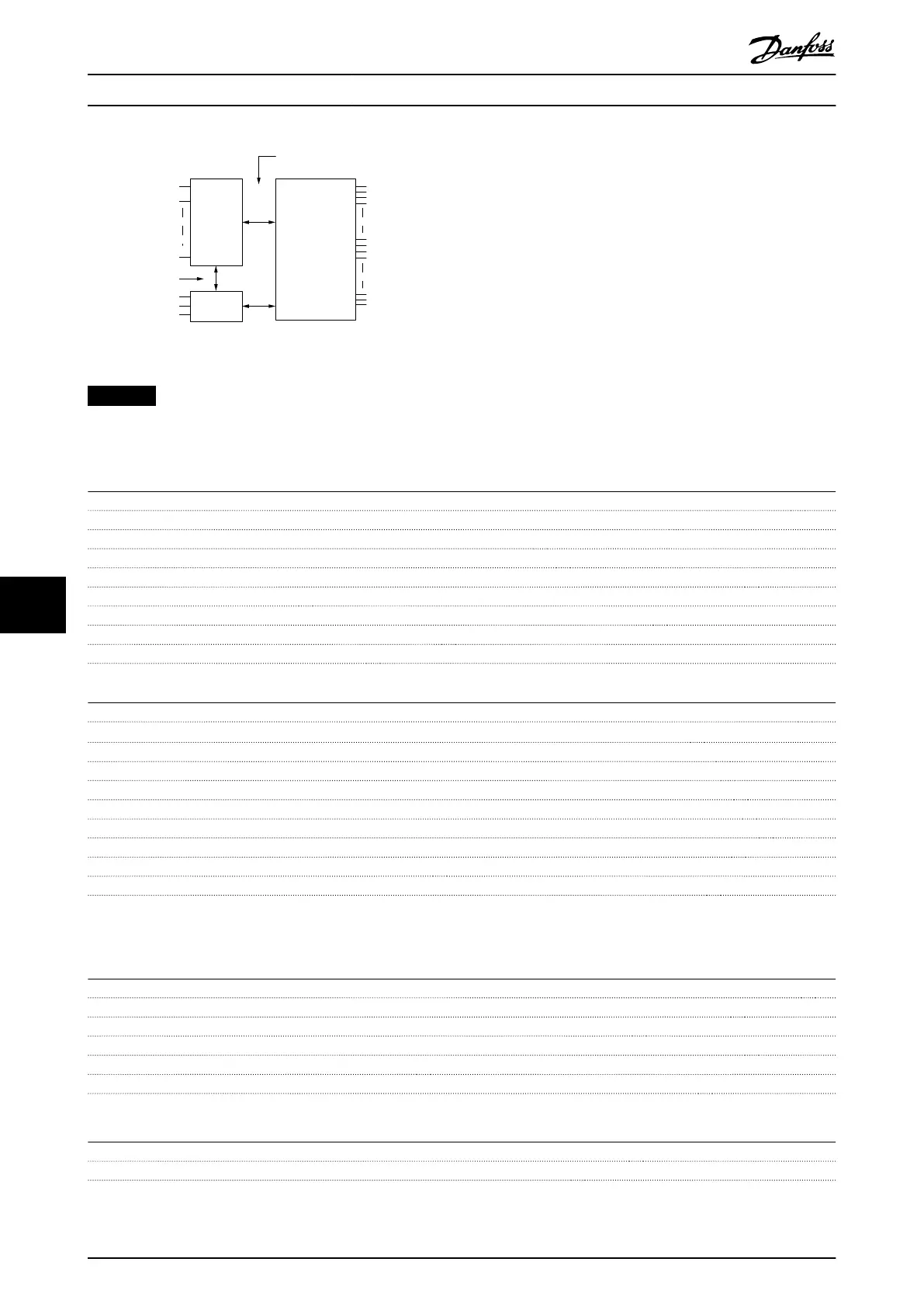
Mains
Functional
isolation
PELV isolation
Motor
DC bus
High
voltage
Control
37
RS485
38
33
130BE837.10
Illustration 9.1 Galvanic Isolation
NOTICE
HIGH ALTITUDE
For installation at altitudes above 2000 m (6562 ft), contact Danfoss hotline regarding PELV.
Pulse inputs
Programmable pulse inputs 2
Terminal number pulse 29, 33
Maximum frequency at terminal 29, 33 32 kHz (push-pull driven)
Maximum frequency at terminal 29, 33 5 kHz (open collector)
Minimum frequency at terminal 29, 33 4 Hz
Voltage level See the section on digital input
Maximum voltage on input 28 V DC
Input resistance, R
i
Approximately 4 kΩ
Pulse input accuracy Maximum error: 0.1% of full scale
Digital outputs
Programmable digital/pulse outputs 1
Terminal number 27
1)
Voltage level at digital/frequency output 0–24 V
Maximum output current (sink or source) 40 mA
Maximum load at frequency output 1 kΩ
Maximum capacitive load at frequency output 10 nF
Minimum output frequency at frequency output 4 Hz
Maximum output frequency at frequency output 32 kHz
Accuracy of frequency output Maximum error: 0.1% of full scale
Resolution of frequency output 10 bit
1) Terminal 27 can also be programmed as input.
The digital output is galvanically isolated from the supply voltage (PELV) and other high-voltage terminals.
Analog outputs
Number of programmable analog outputs 1
Terminal number 42
Current range at analog output 0/4–20 mA
Maximum resistor load to common at analog output 500 Ω
Accuracy on analog output Maximum error: 0.8% of full scale
Resolution on analog output 10 bit
The analog output is galvanically isolated from the supply voltage (PELV) and other high-voltage terminals.
Control card, 24 V DC output
Terminal number 12, 13
Maximum load 100 mA
The 24 V DC supply is galvanically isolated from the supply voltage (PELV). However, the supply has the same potential as the
analog and digital inputs and outputs.
Specications
VLT
®
Midi Drive FC 280
58 Danfoss A/S © 10/2017 All rights reserved. MG07A402
99
 Loading...


