2. Insert the optional I/O module into its slot from the inside of your computer.
3. Connect the I/O cable to the connector on the system board.
4. Replace the two (M3x3) screws that secure the optional I/O module (HDMI/DP/PS2) or two (M2x5) cross type screws
that secure the optional I/O module (VGA/Serial) to the computer chassis.
Next steps
1. Install the side cover.
2. Follow the procedure in After working inside your computer.
Optional Type-C module
Removing the optional Type-C module
Prerequisites
1. Follow the procedure in Before working inside your computer.
2. Remove the side cover.
About this task
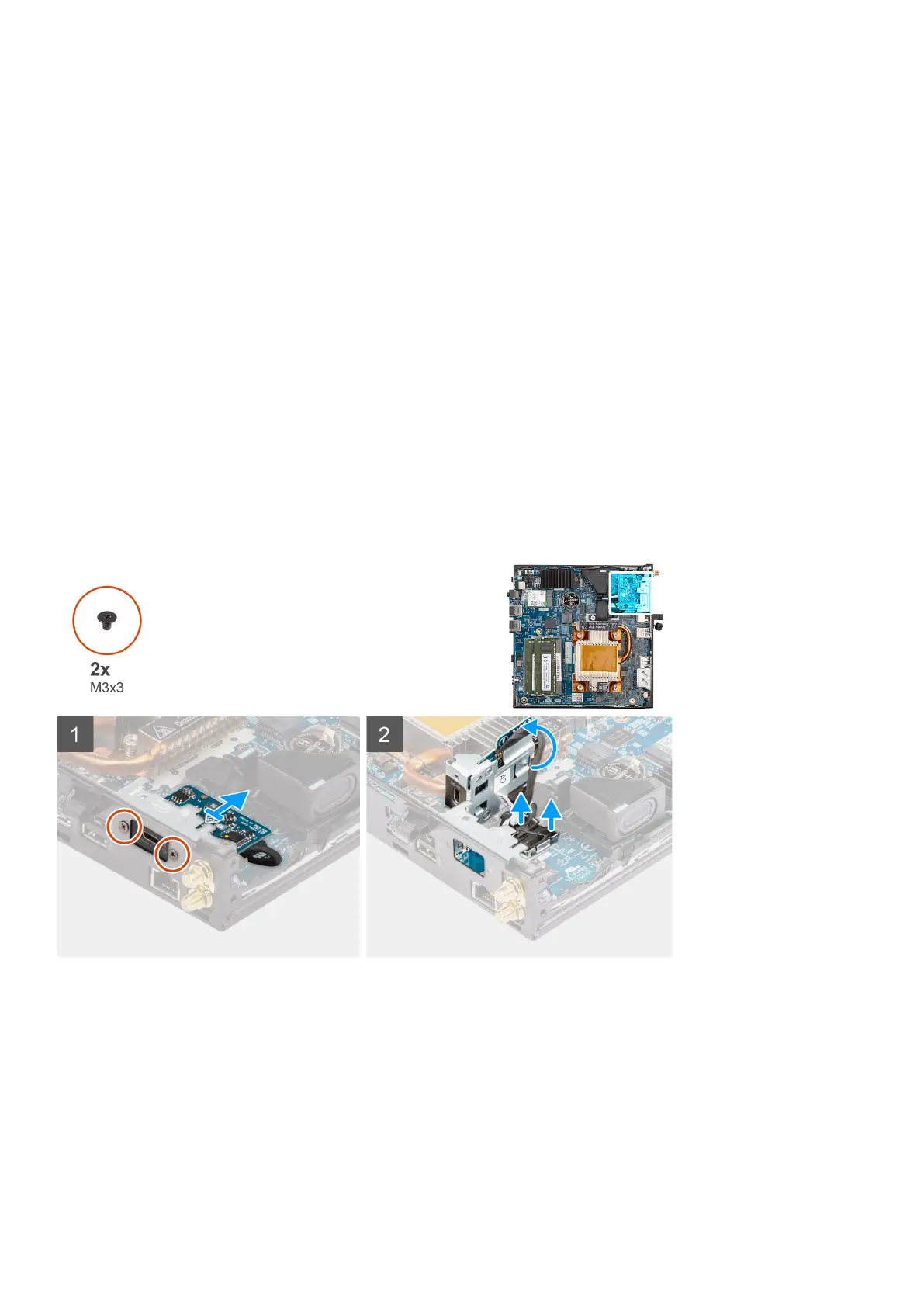
The following images indicate the location of the optional Type-C module and provide a visual representation of the removal
procedure.
Steps
1. Remove the two (M3x3) screws that secure the optional Type-C module.
2. Remove the optional Type-C module from its slot on the chassis.
3. Lift and hold the optional Type-C module in place above the system board.
4. Disconnect the Type-C DisplayPort cable from the system board.
5. Disconnect the Type-C USB cable from the system board.
6. Remove the optional Type-C module from the computer.
Removing and installing Field Replaceable Units (FRUs)
61
 Loading...