The Z9000 System | 13
The Z9000 system LEDs are:
• System status (SYS)
• Power status (PSU)
• Alarm status (ALM)
• System locator beacon (LOC)
• System reset (Reset)
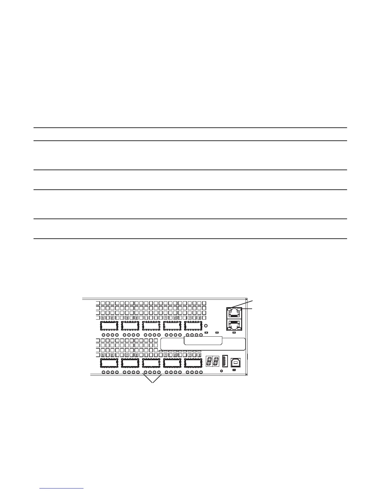
As shown in the following figure, the Z9000 includes status indicator LEDs for each port. These ports are
described in
Table 2-4
. When the QSFP+ ports are operating in 40G mode, the left-most LED for the port
is lit. When the ports are operating in 4x10G mode, only the LEDs associated with an active port are lit.
Figure 2-4. Port LEDs
Table 2-3. System LED Displays
Label
LED Color/Display Description
System status (SYS)
Located on I/O panel
Off
Green solid
Amber solid
No power
Normal operation
Error during boot-up
Power status (PSU0, PSU1)
Located on I/O panel
Green solid
Amber solid
Normal operation
Power supply missing or failed
Alarm status (ALM)
Located on I/O panel
Off
Amber solid
Red solid
No alarm
Minor alarm
Critical alarm
System locator (LOC)
Located on I/O panel
Off
Blue solid
No activity
System beacon/locator
Managemen
port LEDs
QSFP+
port LEDs
 Loading...