Install the Z9000 | 21
Attach the Ground Cable
Use a single M4x0.7 screw to attach the ground cable to the system. The cable itself is not included with
the Z9000. To properly ground the system, Dell Force10 recommends using a 6AWG one-hole lug, #10
hole size, 63" spacing (not included in shipping). The one-hole lug must be a UL recognized, crimp-type
lug.
NOTE: The rack installation “ears” are not suitable for grounding.
CAUTION: Grounding conductors must be made of copper. Do not use aluminum conductors.
To connect the ground cable to the system, follow these steps:
NOTE: Coat the one-hole lug with an anti-oxident compound prior to crimping. Also, bring any un-plated
mating surfaces to a shiny finish and coat it with an anti-oxidant prior to mating. Plated mating surfaces must
be clean and free from contamination.
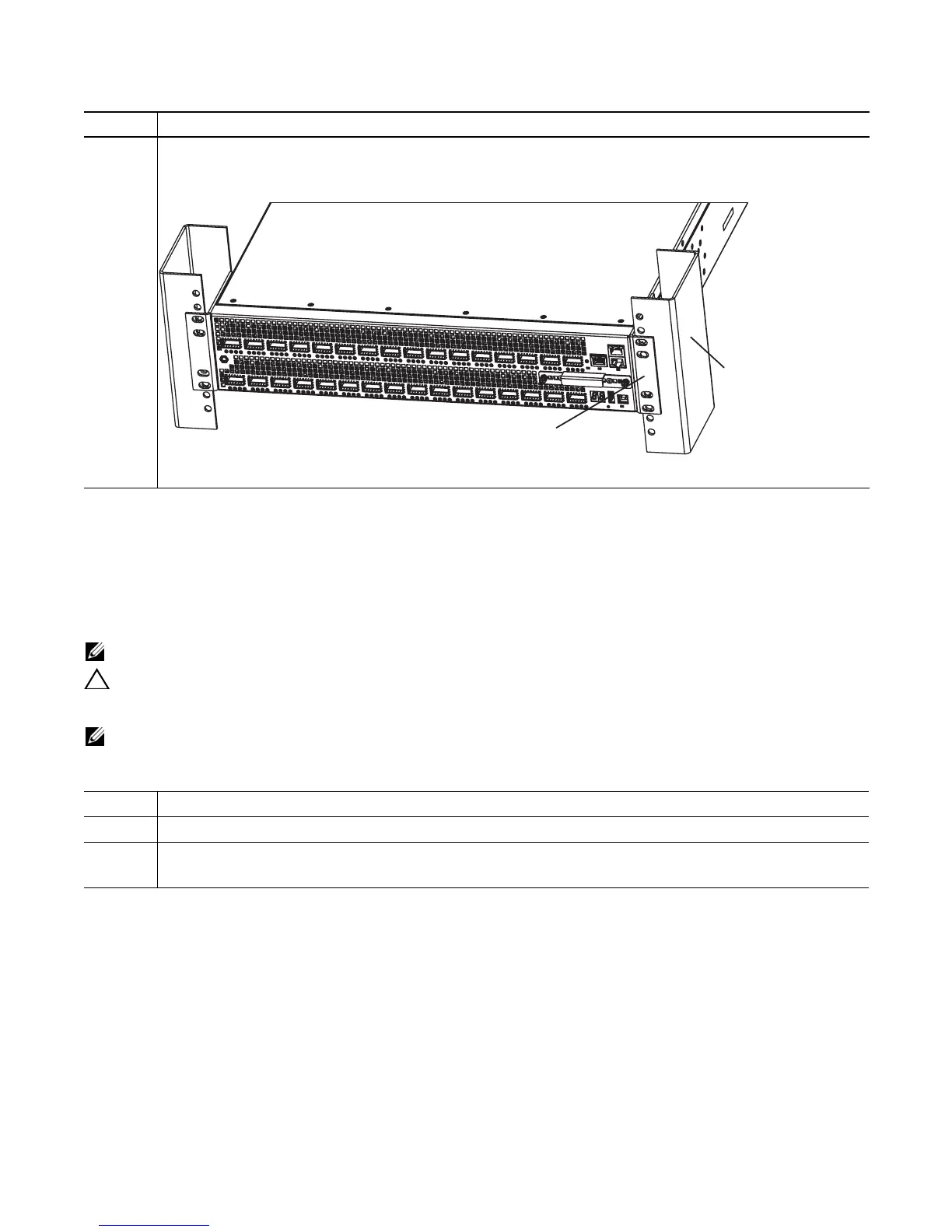
1 Attach the bracket “ears” to the rack or cabinet posts using two screws for each bracket. Ensure the screws are
tightened firmly. The example shows the mounting on the I/O side, but you can use either side.
Step Task
1 Take the one M4x0.7 screw from the package.
2 Cut the cable to the desired length. The cable length must facilitate the proper operation of the fault interrupt
circuits. Dell Force10 recommends using the shortest cable route allowable.
Step Task (continued)
Rack/Cabinet
Post
Rack/Cabinet
Mounting Ears
I/O side
 Loading...