2. Hold the display assembly against the edge of the table, aligning the screw holes on the display hinges with the screw holes
on the palm-rest and keyboard assembly.
3. Replace the five screws (M2.5x5) that secure the display hinges to the palm-rest and keyboard assembly.
4. Connect the display cable to the connector on the system board and close the latch.
5. Adhere the tape that secures the display-cable connector latch to the system board.
Next steps
1. Install the base cover.
2. Follow the procedure in After working inside your computer.
Power-adapter port
Removing the power-adapter port
Prerequisites
1. Follow the procedure in Before working inside your computer.
NOTE: Ensure that your computer is in Service Mode. For more information see, step 6 in Before working inside your
computer.
2. Remove the base cover.
3. Remove the display assembly.
4. Remove the heat sink.
About this task
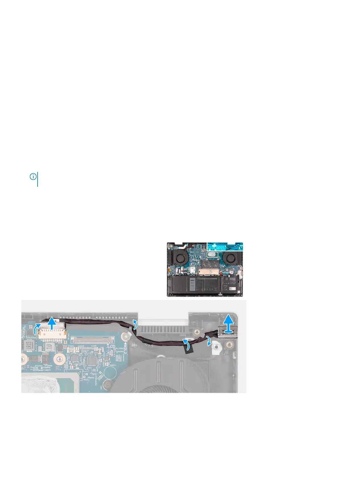
The following image(s) indicate the location of the power-adapter port and provides a visual representation of the removal
procedure.
Steps
1. Peel the tape that secures the power-adapter port cable to the system board.
2. Disconnect the power-adapter port cable from the system board.
3. Peel the tape that secures the power-adapter port cable to the palm-rest and keyboard assembly.
Removing and installing components
31
 Loading...