About this task
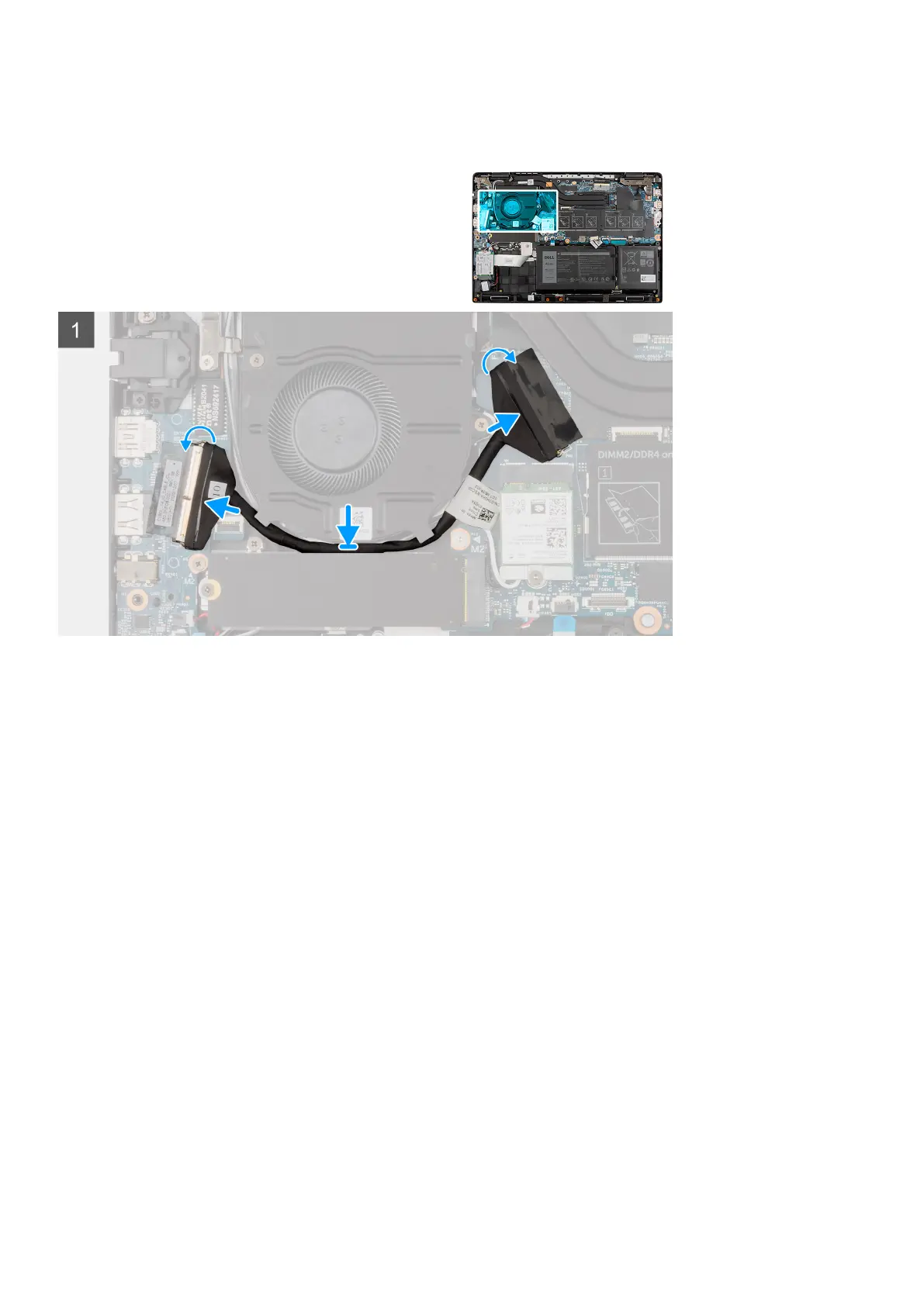
The following image indicates the location of the I/O cable and provides a visual representation of the installation procedure.
Steps
1. Route the I/O cable through the routing guides and adhere the adhesive tape to secure the I/O cable in place.
2. Connect the I/O cable to the connector on the system board, adhere the adhesive tape, and close the latch.
3. Connect the I/O cable to the connector on the I/O board, adhere the adhesive tape, and close the latch.
Next steps
1. Install the base cover.
2. Exit the service mode
3. Install the microSD-card.
4. Install the SIM card tray for 4G LTE enabled systems.
5. Follow the procedure in after working inside your computer.
Display assembly
Removing the display assembly
Prerequisites
1. Follow the procedure in before working inside your computer.
2. Remove the microSD-card.
3. Remove the SIM card tray for 4G LTE enabled systems.
4. Enter the service mode.
5. Remove the base cover.
6. Remove the M.2 SSD for systems enabled with 4G LTE.
7. Remove the M.2 SSD conversion bracket for systems enabled with 4G LTE.
Removing and installing components
49

 Loading...