EasyManuals Logo

Dell OptiPlex 960 User Manual

Dell OptiPlex 960
146 pages
To Next Page IconTo Next Page
To Previous Page IconTo Previous Page
Page #21 background image
Back to Contents Page
Dell™Optiplex™960MiniTower/Desktop/SmallFormFactorServiceManual
Processor
Processor
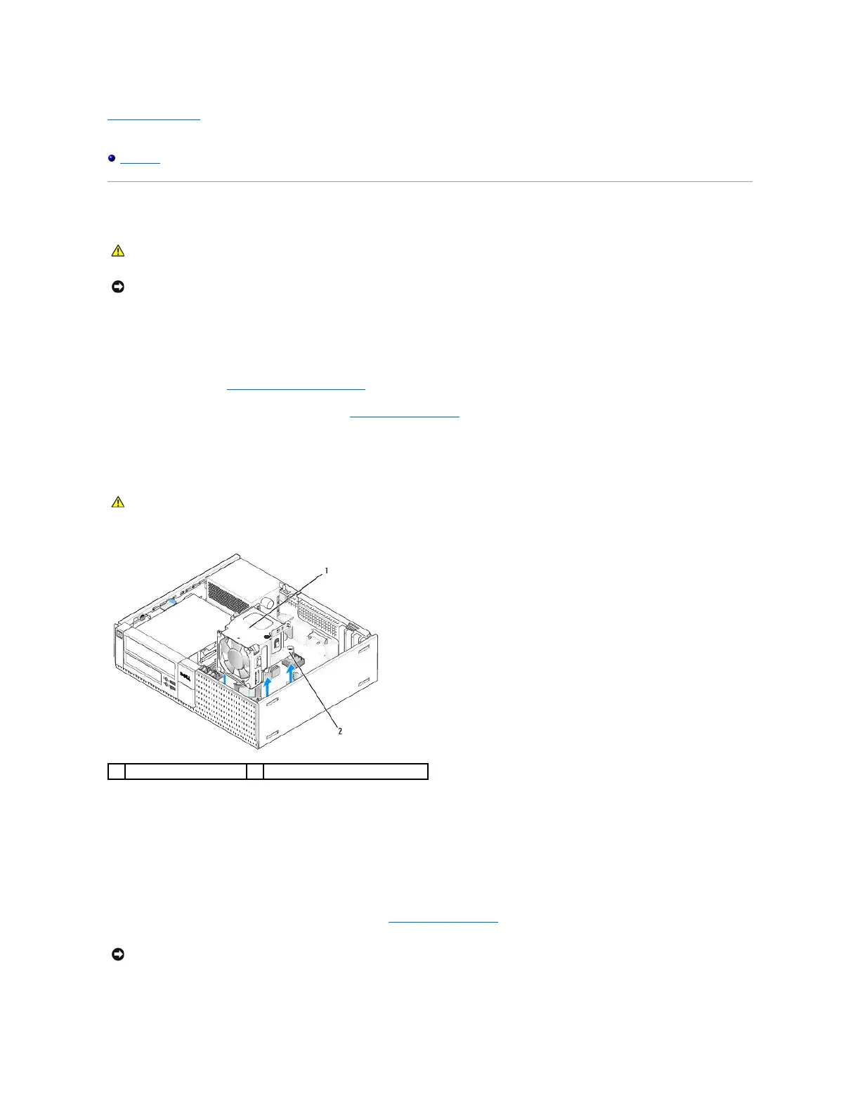
Removing the Heatsink Assembly
The heatsink assembly is comprised of the heatsink and the fan and shroud assembly.
1. Perform the procedure Before Working on Your Computer.
2. Disconnect the fan cable from the system board (see System Board Components).
3. If cables are routed through the cable guides on the back of the fan shroud, remove them from the guides.
4. Loosen the four captive screws, one on each corner of the heatsink assembly.
5. Lift the heatsink assembly upward to remove it from the computer. Lay the heatsink down on its side to avoid contaminating the thermal solution.
Replacing the Heatsink Assembly
1. Lower the heatsink assembly into the computer, aligning the captive screws with the retainers screw holes in the system board. Ensure that the fan
cable is routed to the right side of the heatsink assembly.
2. Tighten the four captive screws to secure the heatsink assembly.
3. Plug the fan cable into its connector on the system board (see System Board Components).
CAUTION: Before working inside your computer, read the safety information that shipped with your computer. For additional safety best
practices information, see the Regulatory Compliance Homepage at www.dell.com/regulatory_compliance.
NOTICE: To prevent static damage to components inside your computer, discharge static electricity from your body before you touch any of your
computer's electronic components. You can do so by touching an unpainted metal surface on the computer chassis.
CAUTION: The heatsink assembly may be very hot during normal operation. Be sure that it has had sufficient time to cool before you touch it.
1
heatsink assembly
2
captive screw housing (4)
NOTICE: Ensure that the heatsink assembly is correctly seated and secure.

Table of Contents

Other manuals for Dell OptiPlex 960

Questions and Answers:

Question and Answer IconNeed help?

Do you have a question about the Dell OptiPlex 960 and is the answer not in the manual?

Dell OptiPlex 960 Specifications

General IconGeneral
Tcase72.4 °C
Bus typeFSB
SteppingE0
Processor cache6 MB
Processor cores2
Processor modelE8400
System bus rate- GT/s
Processor familyIntel® Core™2 Duo
Processor seriesIntel Core 2 Duo E8000 Series
Processor socketLGA 775 (Socket T)
Processor codenameWolfdale
Processing Die size107 mm²
Processor frequency3 GHz
Processor cache typeL2
Processor lithography45 nm
Processor manufacturerIntel
Processor front side bus1333 MHz
Processor operating modes64-bit
ECC supported by processorNo
Thermal Design Power (TDP)65 W
Number of processors installed1
CPU multiplier (bus/core ratio)9
Number of Processing Die Transistors410 M
Internal memory4 GB
Memory clock speed800 MHz
Internal memory typeDDR2-SDRAM
Maximum internal memory16 GB
Memory layout (slots x size)2 x 2 GB
HDD speed7200 RPM
HDD interfaceSATA
Optical drive typeDVD-RW
Total storage capacity250 GB
Networking featuresGigabit Ethernet
Graphics card familyAMD
Compliance industry standardsIEEE 802.3, IEEE 802.3u, IEEE 802.3ab
Discrete graphics card modelAMD Radeon HD 3470
Maximum graphics card memory- GB
On-board graphics card modelNot available
Discrete graphics card memory256 GB
Operating system installedWindows 7 Professional
Microphone inYes
USB 2.0 ports quantity10
Firewire (IEEE 1394) ports0
Ethernet LAN data rates10, 100, 1000 Mbit/s
Chassis typeSFF
Product colorBlack
Product typePC
Processor codeSLB9J
Processor ARK ID33910
Processor package size37.5 x 37.5 mm
Weight and Dimensions IconWeight and Dimensions
Depth323 mm
Width85 mm
Height289 mm
Weight5900 g

Related product manuals