3. Remove the nineteen screws (M1.6x1.7) and six screws (M1.6x1.4) securing the keyboard assembly to the computer.
4. Carefully lift the keyboard assembly to remove it from the computer.
5. Remove the two screws (M1.6x1.7) that secure the keyboard to the keyboard support plate.
6. Separate the keyboard from the keyboard support plate.
NOTE: If the keyboard support plate is replaced, transfer the re-usable rubber filler (for WLAN, 4G WWAN) or thermal
pad (for 5G WWAN) over to the new keyboard support plate.
Installing the keyboard
CAUTION: The information in this installation section is intended for authorized service technicians only.
Prerequisites
If you are replacing a component, remove the existing component before performing the installation procedure.
About this task
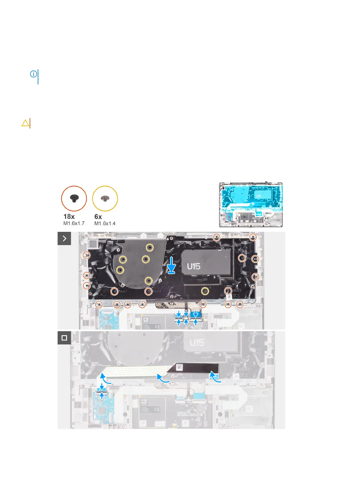
The following images indicate the location of the keyboard and provide a visual representation of the installation procedure.
Figure 81. Installing the keyboard
Removing and installing Field Replaceable Units (FRUs)
109
 Loading...