System board
Removing the system board
CAUTION: The information in this removal section is intended for authorized service technicians only.
Prerequisites
1. Follow the procedure in Before working inside your computer.
2. Remove the base cover.
3. Remove the M.2 2230 solid-state drive.
4. Remove the 2-cell battery or the 3-cell battery, whichever is applicable.
5. Remove the heat-sink.
About this task
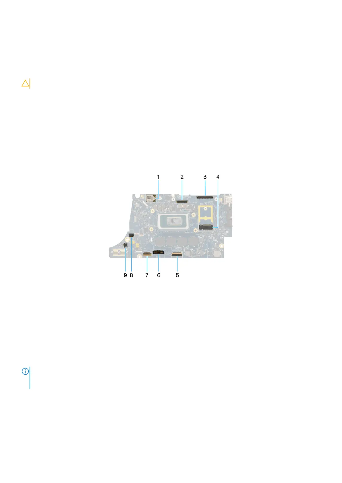
The following image indicates the connectors on your system board.
Figure 58. System Board Calllout
1. WWAN card
2. LCD connector
3. Touchscreen and IR-camera cable connector
4. M.2 solid state drive connector
5. USH daughterboard FFC connector
6. Battery cable connector
7. Click pad FFC connector
8. Coin-cell battery cable connector
9. Fan connector
NOTE:
For computers shipped without a WWAN card, a 4G/5G WWAN shielding cover and WWAN bracket (for 4G WWAN
card) is preinstalled to the computer. As a result, follow the steps in the WWAN card removal/installation section to remove
the WWAN shielding cover and WWAN bracket before removing the system board.
The following images indicate the location of the system board and provide a visual representation of the removal procedure.
Removing and installing Field Replaceable Units (FRUs)
87