46 Installing System Components
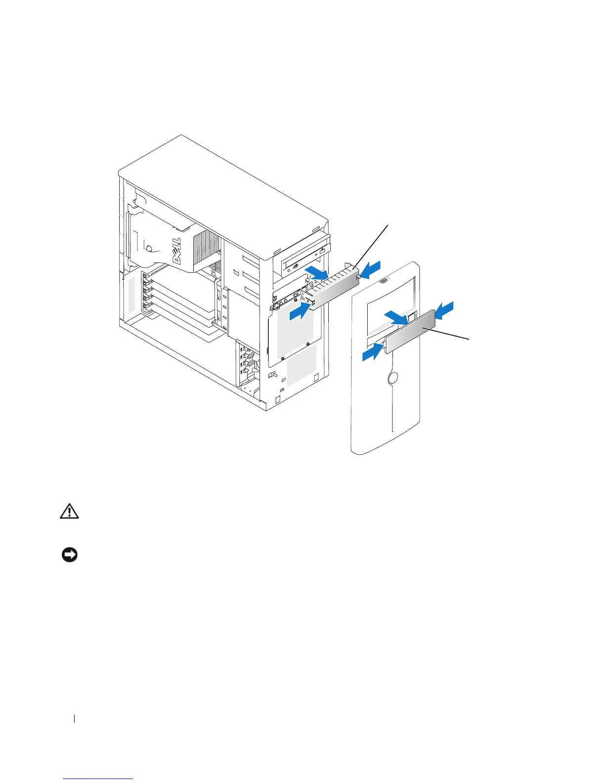
Figure 3-4. Removing the Front-Panel Drive Inserts
Installing the Front-Panel Drive Inserts
CAUTION: Only trained service technicians are authorized to remove the system cover and access any of the
components inside the system. Before performing any procedure, see your Product Information Guide for complete
information about safety precautions, working inside the computer, and protecting against electrostatic discharge.
NOTICE: You must install both inserts in an empty 5.25-inch drive bay to maintain Federal Communications
Commission (FCC) certification of the system. The inserts also help keep dust and dirt out of the system.
1
Install the chassis drive insert by sliding the insert into the chassis until tabs on the side of the insert
snap into place. See Figure 3-4.
2
Install the bezel drive insert by sliding the insert into the bezel until the tabs on the side of the insert
snap into place. See Figure 3-4.
3
Install the bezel. See "Installing the Bezel" on page 47.
4
Reconnect the system to its electrical outlet and turn the system on, including any attached
peripherals.
1 chassis drive insert 2 bezel drive insert
1
2
 Loading...