66 Installing System Components
Removing the Front System Fan
CAUTION: Only trained service technicians are authorized to remove the system cover and access any of the
components inside the system. Before performing any procedure, see your Product Information Guide for
complete information about safety precautions, working inside the computer, and protecting against electrostatic
discharge.
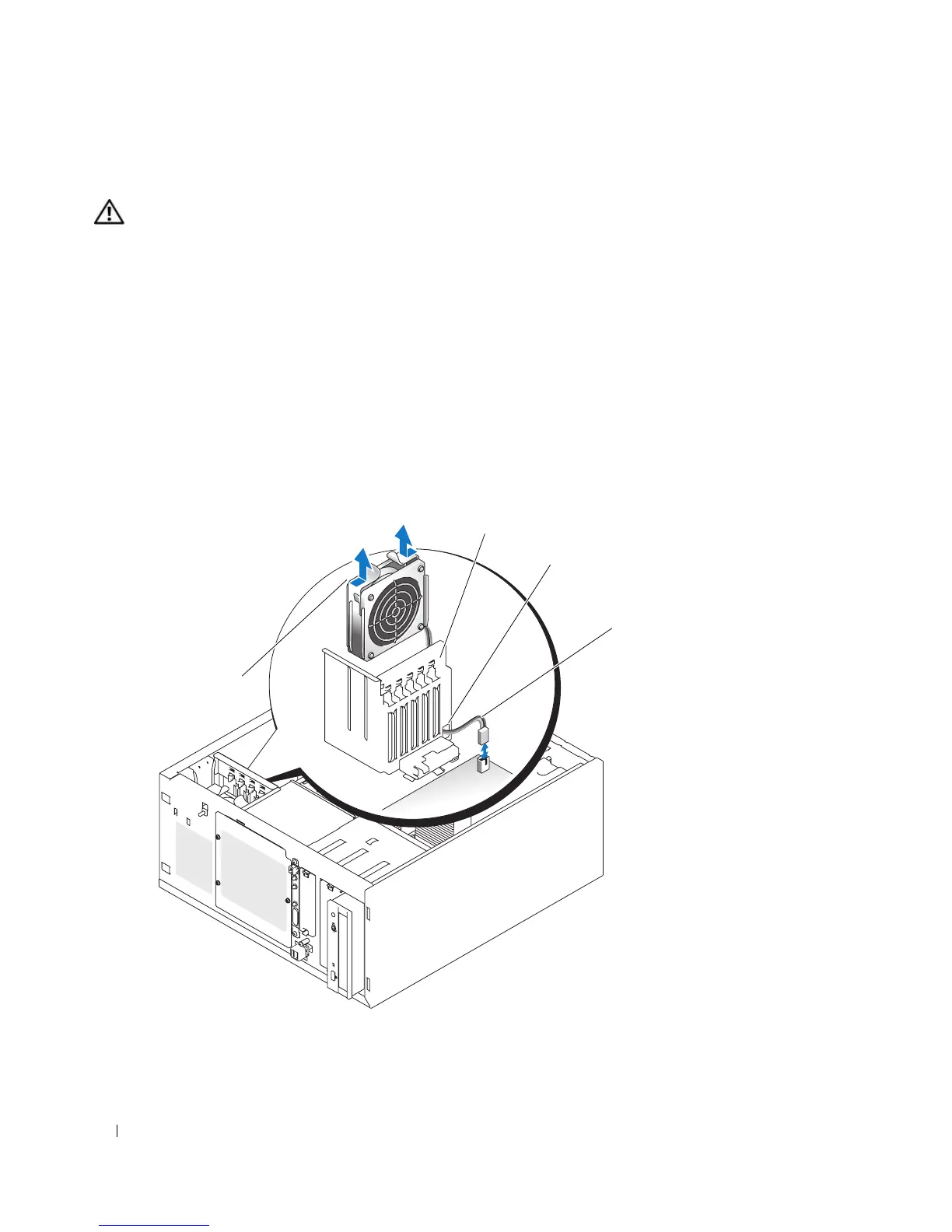
Figure 3-15 illustrates the front system fan inside the system and the fan cable routing hole in the
expansion-card guide bracket.
1
Turn off the system, including any attached peripherals, and disconnect the system from the electrical
outlet.
2
Open the system. See "Opening the System" on page 43.
3
Disconnect the fan power cable from the FRONT_FAN connector on the system board. See "System
Board Connectors" on page 118.
Figure 3-15. Front System Fan Power Cable
1 expansion-card guide bracket 2 cable routing hole 3 fan power cable
4 release tabs (2)
2
3
1
4
 Loading...