101 PowerEdge FX2 – FN I/O Module – VLT Deployment Guide | Version 2.2
Enabled on all ports (Uplink created
by default based on LACP PDU)
All server and uplink ports are in all
VLANs
Standalone Mode default settings
By default, network ports on the PowerEdge FC-Series servers installed in the FX2 chassis remain
down until the uplink port channel is operational on the FN IOM. This is due to a feature called Uplink
Failure Detection whereby the FN IOM disables the downstream links when upstream connectivity
fails.
Note: For more information on Uplink Failure Detection and all other configuration settings, see the
Dell PowerEdge FN I/O Module Configuration Guide.
E.1 Configure interfaces and the port channel on the upstream
switch
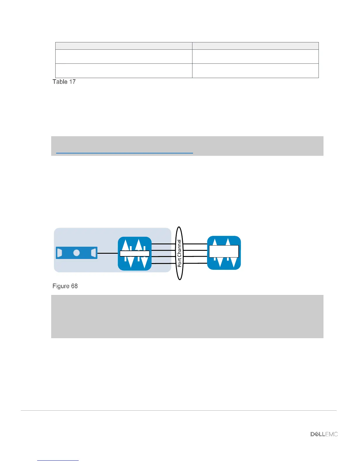
This step provides the commands used to configure port channels on common upstream switches that
may be connected to the FN IOM (Figure 68).
Te x/x
FX2 Chassis
Blade
Upstream
Switch
Te 0/9
Te 0/11
Te 0/10
Te 0/12
Port 1
Port 2
Port 3
Port 4
FN IOM
Interface and port channel view
Note: The diagram above (Figure 68) applies to the FN 410S and FN 410T. If you are using the
FN 2210S in its default configuration, you only use Ethernet ports Te 0/11 and Te 0/12 in the uplink
port channel since ports Te 0/9 and Te 0/10 have been replaced by fibre channel ports. Ports 0/9 and
0/10 can be converted to Ethernet ports if desired by typing the command: stack-unit 0 port-
group 0 portmode ethernet
By default on the FN IOM, the external Ethernet ports are preconfigured in port channel 128 with
LACP enabled. Port channel 128 is in hybrid (trunk) mode.
For the downstream (server) ports on the FN IOM to come up, port channel 128 must be up. Port
channel 128 comes up when connected to a properly configured port channel on an upstream switch.
 Loading...