35 PowerEdge FX2 – FN I/O Module – VLT Deployment Guide | Version 2.2
7.1.2 Configuring the VLTi peer link
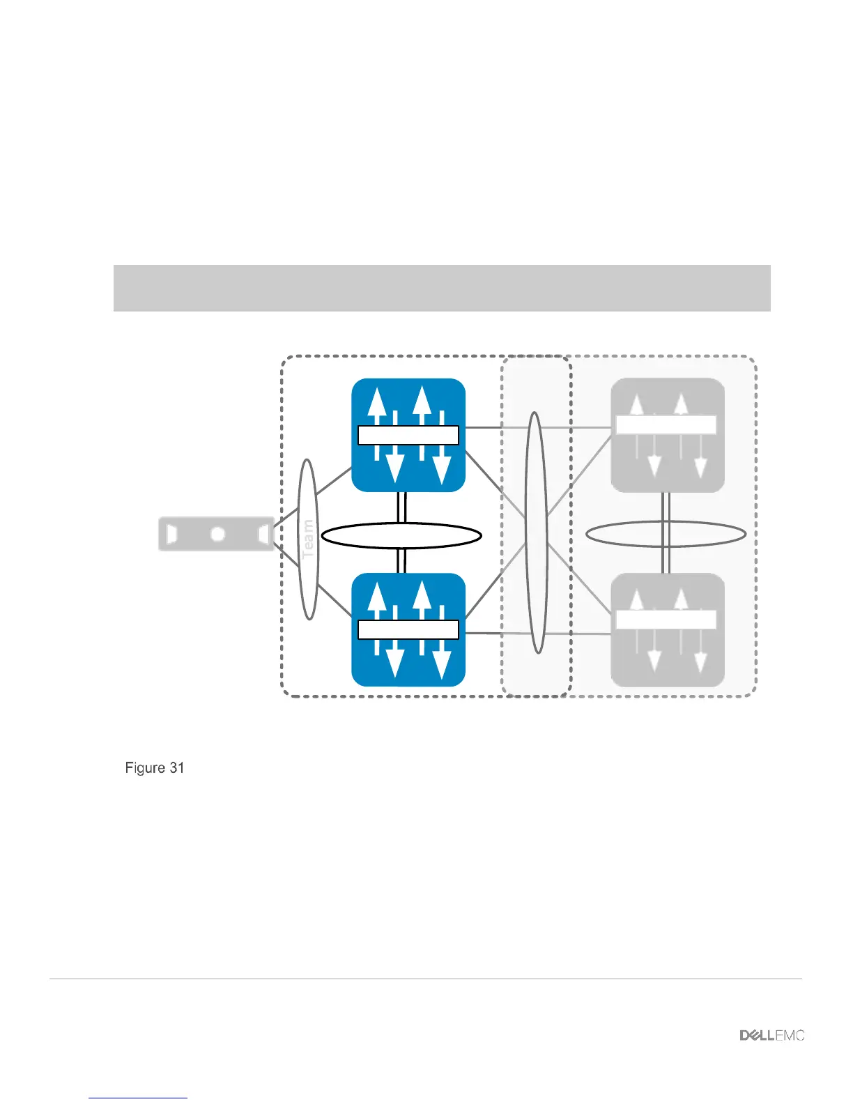
In this section, the VLTi peer link is configured (Figure 31).
First, the port channel that will be assigned as the VLTi peer link is created and channel members are
assigned. Next, in Full Switch mode, a VLT domain is created. The peer link is then assigned and the
backup destination is configured to enable heartbeat communications over the management network.
Finally, a unit ID is specified to ensure that the two IOM peer switches are assigned primary or
secondary roles.
Note: In this example, the port channel number matches on both sides. This is not a strict
requirement.
VLT Domain VLT Domain 2
VLTi (Po 127)
FC630 Server
Te 0/9 Te 0/10
FN410S-A1
FN410S-A2
S4810-A1
Te 0/10Te 0/9
S4810-A2
VLTi peer-link configuration

 Loading...