Chapter 4 - Operation
the left rear corner of the cabinet (when viewed from the rear door) near the vertical cable duct where
the connection is made to the LCN MAU. The cable between the LCNP4E board and the LCN MAU is 2
meters in length.
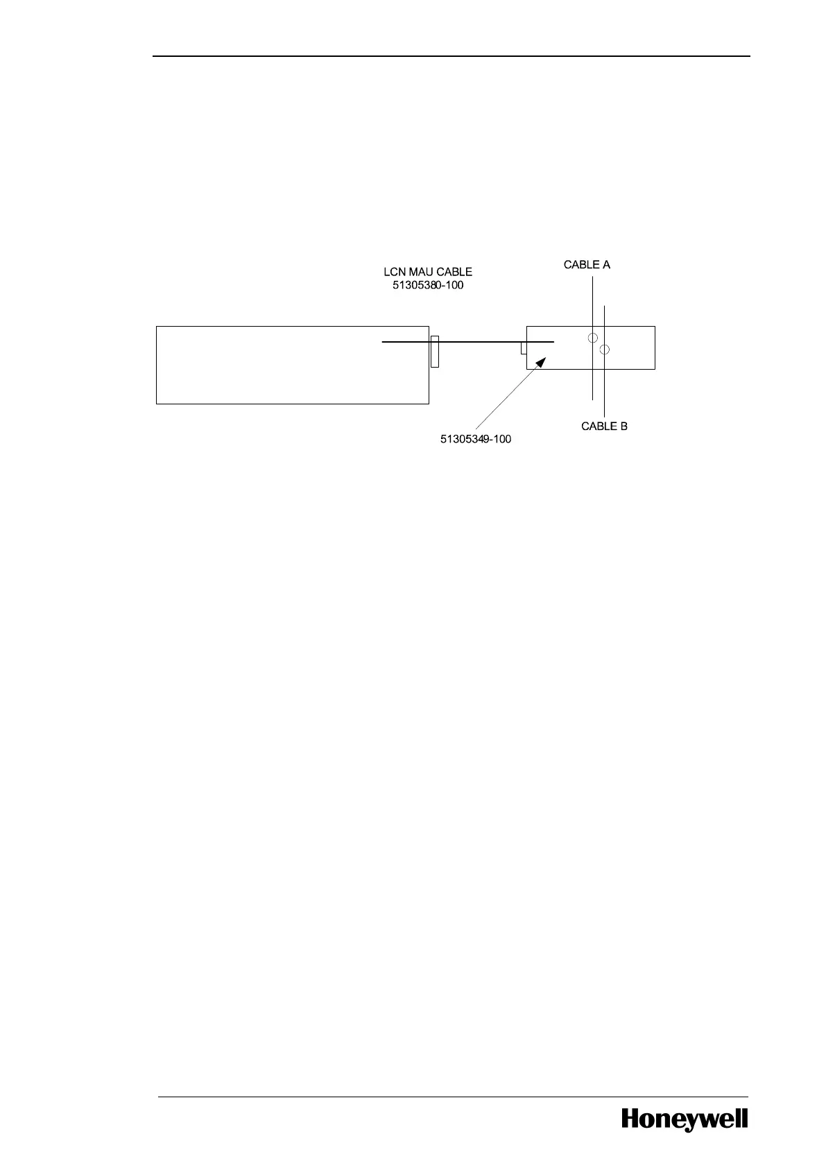
4.2.3 LCN connections
The LCN Cable A and Cable B connections are made through a single cable from the LCNP4E board to
the LCN Media Access Unit (MAU) contained in a metal housing. The following illustrates a LCN MAU
to LCN cabling.
4.2.4 LCN network
The connection to the LCN is made through a Local Control Network Processor (LCNP4E) card. The
LCNP4e card is a Honeywell PWA that allows the TPS Operator Station to emulate Universal Stations.
This card provides the communication path for the Operator Station to other LCN modules. The
LCNP4E consists of an LCNP4E Card, a MAU cable and the LCN MAU (Media Access Unit). The
LCNP4e card is a PCIe card and is located in PCI-ex8 slot 1. The LCNP4E, MAU and MAU cable are
required on Server Platform. The LCN node address must be set to the address the customer wants. If
the LCN address is not known then the node address must be set to zero (0). Setting the address to
zero (0) allows the node to be connected to the LCN without the risk of an address conflict with some
other node. This is consistent with the current LCN standard procedure. The Honeywell server platform
uses only a digital system clock. When the Dell R320 platform is added to an existing system that
contains nodes running analog clocks that system must have at least two (2) KxLCN boards for
analog/digital clock translation. The model number for the LCNP4E is TP-LCNP04.
4.2.5 MAU connection
Connect the MAU to both Cable A and Cable B coax T-connector as illustrated in the following Figure.
Figure 4.3 Connect the MAU to Cable A and Cable B
- 40 -

 Loading...