Dell
Dell PowerEdge R910 Technical Guide 19
through a software control (through server management functions). The power system is compatible
with industry standards, such as ACPI and the Microsoft Windows Server Hardware Design Guide.
If not using all four power supplies, it is preferred that the power supply be installed starting from
PS1 bay in order to avoid power loss in the PDB copper planes. However, there is nothing that
prevents the use of the rest of the bays in that case. The empty bays should be populated with the
PS sheet metal blanks for thermal reasons.
The system power distribution consists of one, two, three or four AC-to-DC power supplies connected
to the planar through the PDB. The power supply only provides +12V and +12Vaux. The power
supplies connect indirectly to the planar through the power distribution board (PDB). There is a
power cable that connects the PDB and the backplane. Another cable also connects the PDB to the
optical and/or tape drives. There are no cables involved for delivering the power from the power
supplies to the motherboard.
The 12V power is then distributed to the rest of the subsystems like the backplane and optical drive
from the motherboard using cables. There are several voltage regulators in the system to supply
different voltage levels needed by different logic devices.
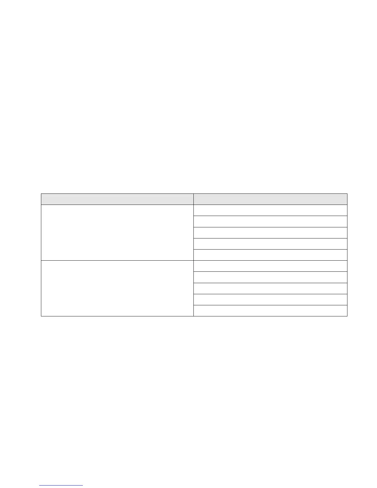
R910 has four power supply bays. Power supply system configurations are shown in Table 4.
Table 4. Power Supply System Configurations
High-output power supply (1100W)
Non-redundant configuration (1+0)
Redundant Energy Optimal configuration (1+1)
Non-redundant Full-power configuration (2+0)
Failover configuration (2+1)
Redundant Full-power configuration (2+2)
Energy Smart power supply (750W)
Non-redundant configuration (1+0)
Redundant Energy Optimal configuration (1+1)
Non-redundant Full-power configuration (2+0)
Failover configuration (2+1)
Redundant Full-power configuration (2+2)
There are two different redundancy modes with two of the power supplies. One is (2+0) non-
redundant capable of running full system configuration, and the other is (1+1) redundant running
limited configuration. You can switch the mode between (1+1) and (2+0) using the iDRAC GUI only for
the two power supply cases, depending on if the system is capable of supporting the new mode or
not. The other modes of redundancy are automatics based on the functional supplies present when
AC is applied and the system is powered on.
In the (2+2) mode, if the power supplies are evenly split across two separate grids on the AC line
side, then this mode would also be considered “AC or Grid” redundant in addition to power.

 Loading...