EasyManuals Logo

Dell PowerEdge R910 Technical Guide

Dell PowerEdge R910
63 pages
To Next Page IconTo Next Page
To Previous Page IconTo Previous Page
Page #30 background imageLoading...
Page #30 background image
Dell
Dell PowerEdge R910 Technical Guide 30
Platform Environmental Control Interface (PECI)
Intel Dynamic Power Mode Manager
I/O interrupt controller
SMBus 2.0 controller
Low Pin Count (LPC) interface to Super I/O, Trusted Platform Module (TPM), and SuperVU
Serial Peripheral Interface (SPI) support for up to two devices (R910 BIOS flash device is
connected to the ICH10 using SPI)
8.6 PCI Express Connectors
The R910 planar incorporates four 164-pin PCI Express-style x8 (slots 1, 2, 3 and 5) and three 164-pin
PCI Express-style x16 connectors (slots 4, 6 and 7) for connectivity to the PCIe cards. Only one x16
(slot 7) out of the three physical connectors is electrically x16 as well. The other two (slots 4 and 6)
are electrically x8 using a x16 physical connector for double wide GPGPU adapters.

Table of Contents

Other manuals for Dell PowerEdge R910

Questions and Answers:

Question and Answer IconNeed help?

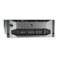
Do you have a question about the Dell PowerEdge R910 and is the answer not in the manual?

Dell PowerEdge R910 Specifications

General IconGeneral
ProcessorUp to four Intel Xeon 7500 series processors
Form Factor4U Rack Server
StorageUp to 16 x 2.5" SAS, SATA, or SSD drives
RAID ControllerPERC H700, PERC H800
NetworkEmbedded Broadcom 5709c Gigabit Ethernet
Power SupplyRedundant 1100W power supplies
Expansion Slots10 PCIe slots
Operating System SupportMicrosoft Windows Server, Red Hat Enterprise Linux, SUSE Linux Enterprise Server, VMware
MemoryUp to 1TB DDR3 (64 DIMM slots)

Related product manuals