A.2 Each inverter require a separate isolated voltage winding. It is forbid to use several
inverters in parallel with one low voltage winding.
A.3 The MV transformer can be oil-type or dry-type.
A.4
It is suggested to have tap changer on the high voltage side to align the voltage level
to medium voltage.
A.5 Higher thermal stress of MV transformer should be taken country settings into
consideration, including the voltage and frequency.
A.6 The transformer is capable of withstanding of max 5% total harmonic current at
nominal power.
A.7 The transformer should be design according to the following inverter rating.
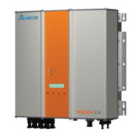
B. The inverter can be connected to MV transformer as following diagram.
Double winding transformer for one inverter
Model No
C1000 350±10% 1650 1650
Nominal Voltage
Range
(Line-Line) (V)
Nominal Output
Current Range @ 50°C (A)
Maximum Output
Current (A)
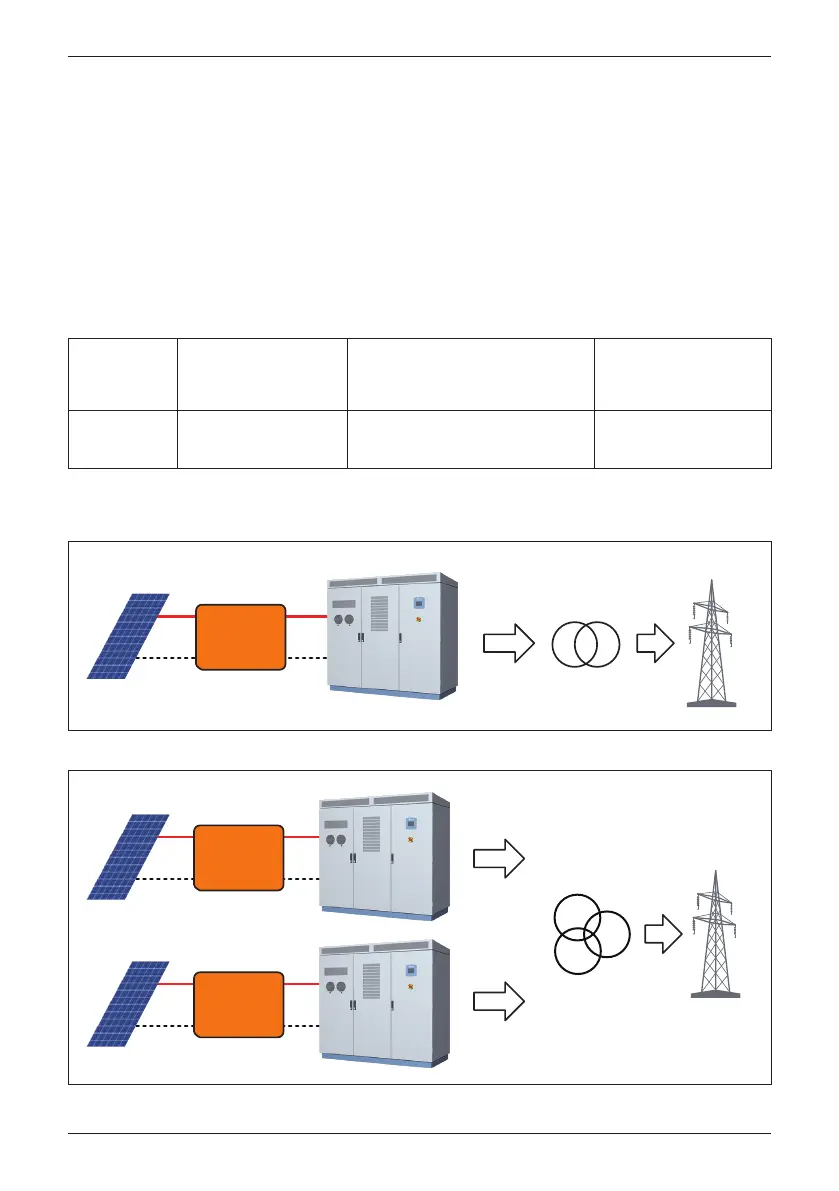
Three winding transformer for two inverters
PV Array Public Grid
3Ph
3 Phase
Transformer
(3 Phase/PE)
DC
Distribution
Box
PV Array
Public Grid
DC
Distribution
Box
PV Array
DC
Distribution
Box
3Ph
3 Phase
Transformer
(3 Phase/PE)
3Ph
(3 Phase/PE)
83
Appendix C: Delta MV Transformer and Auxiliary Power transformer Application Note
 Loading...