Chapter 4 WiringC2000 Plus
4-3
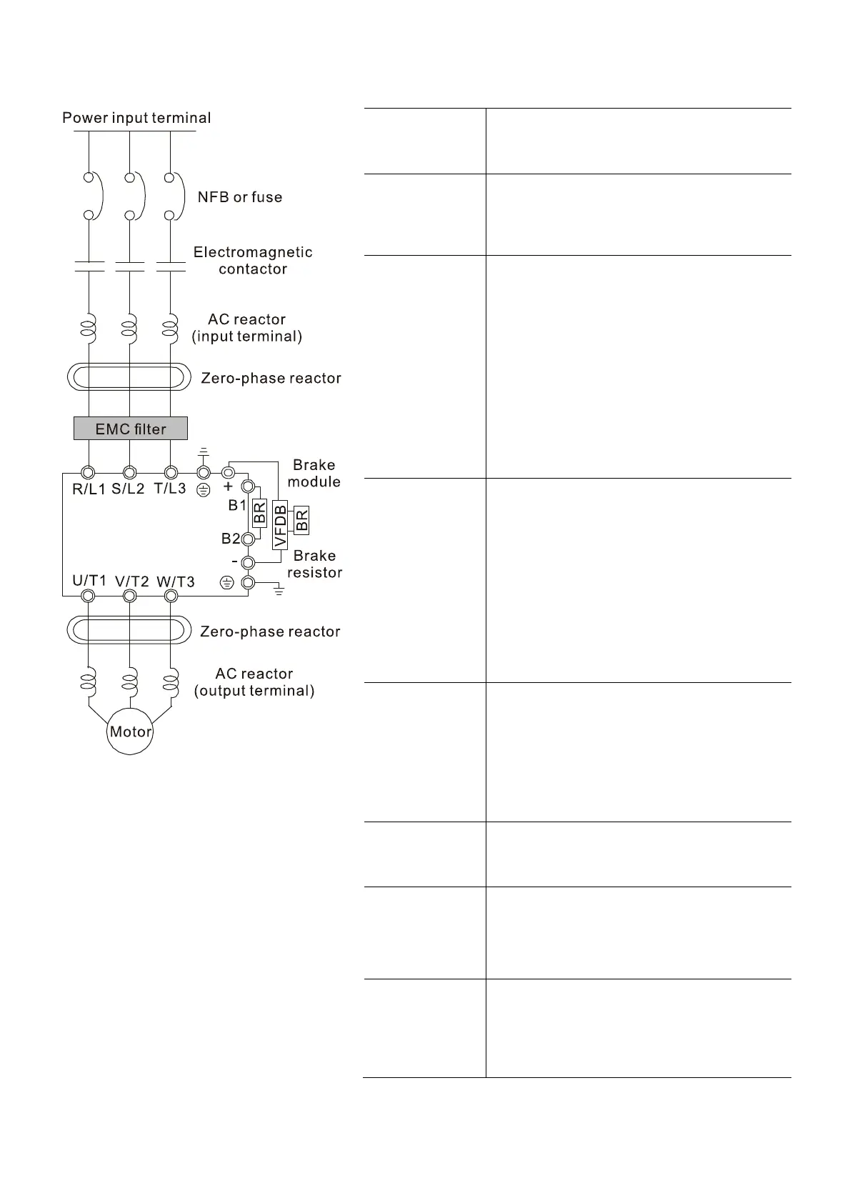
4-1 System Wiring Diagram
Power input
terminal
Supply power according to the rated power
specifications indicated in the manual (refer to
Chapter 9 Specification).
NFB or fuse
There may be a large inrush current during
power on. Refer to Section 7-2 NFB to select
a suitable NFB or Section 7-3 Fuse
Specification Chart.
Electromagnetic
contactor
Switching the power ON/OFF on the primary
side of the electromagnetic contactor can turn
the drive ON/OFF, but frequent switching can
cause machine failure. Do not switch ON/OFF
more than once an hour.
Do not use the electromagnetic contactor as
the power switch for the drive; doing so
shortens the life of the drive.
Refer to Section 7-2 Magnetic Contactor / Air
Circuit Breaker to select the electromagnetic
contactor that meets your requirement.
AC reactor
(input terminal)
When the mains power supply capacity is
greater than 500 kVA, or when it switches into
the phase capacitor, the instantaneous peak
voltage and current generated may destroy the
internal circuit of the drive.
It is recommended that you install an input side
AC reactor in the drive. This also improves the
power factor and reduces power harmonics.
The wiring distance should be within 10 m.
Refer to Section 7-4 AC / DC Reactor for
details. Refer to Chapter 7-4.
Zero phase
reactor
Used to reduce radiated interference,
especially in environments with audio
devices, and reduce input and output side
interference.
The effective range is AM band to 10 MHz.
Refer to Section 7-5 Zero Phase Reactors for
details.
EMC filter
Can be used to reduce electromagnetic
interference. Refer to Section 7-6 EMC
Filter for details.
Brake module
&
Brake resistor
(BR)
Used to shorten the deceleration time of the
motor. Refer to Section 7-1 Brake Resistors
and Brake Units Used in AC Motor Drives for
details.
AC reactor
(output terminal)
The motor cable length affects the size of the
reflected wave on the motor end. It is
recommended that you install an AC output
reactor when the motor wiring length exceeds
the value listed in Section 7-4.
Figure 4-1
Table 4-1
NOTE:
Refer to Section 4-2 Wiring Diagram for
detailed wiring information.
 Loading...