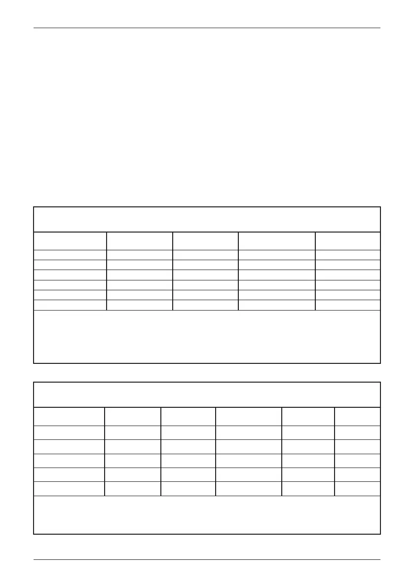
Region
High Voltage 2 (HV2)
High Voltage 1 (HV1)
Near Nominal (NN)
Low Voltage 1 (LV1)
Low Voltage 2 (LV2)
Low Voltage 3 (LV3)
a
While these operating parameters correspond to the Rule 21 parameters, they may be substituted with
operating parameters for other area EPS requirements.
Note 1: Manufacturer may evaluate product over wider ranges of adjustment than those within the table.
Note 2: The table voltage could be either at the PCC or equipment terminals.
Note 3: For LV3 or HV1 the EUT shall cease to energize in not more than 0.16s (and not trip).
This may differ in other SRD(s).
Appendix A-1: Low and High Voltage Ride-Through Set-points and Timing per Table SA9.1
Default operating parameters that correspond to Rule 21 L/HVRT
a
Appendix A-2: Low and High Frequency Ride-Through Set-points and Timing per Table SA10.1
Default operating parameters that correspond to Rule 21 L/HFRT
a
V ≥ 120
110 < V < 120
88 ≤ V ≤ 110
70 ≤ V < 88
50 ≤ V < 70
V < 50
Not Applicable
12s
Indefinite
20s
10s
1s
Not Applicable
Momentary Cessation
Continuous Operation
Mandatory Operation
Mandatory Operation
Momentary Cessation
0.16s
13s
Not Applicable
21s
11s
1.5s
Voltage
(% Nominal Voltage)
Ride-Through Until Operating Mode
Maximum Trip Time
(s)
APPENDIX: Grid Support Utility Interactive Inverters
Appendix A: CA Rule 21
The inverter has pre-programmed control presets intended for use in specific geographic
areas. They include:
• Rule 21 – Preset all required controls to meet the F/VRT specifications that satisfy
CA Power Tariff Rule 21
• HECO A – Presets all required controls to meet the for the Hawaiian Islands of O’ahu,
Hawai’i Island, and Maui
• HECO B – Presets all required controls to meet the F/VRT specifications for the
Hawaiian Islands of Moloka’i and Lana’i
The following sections provide details of the settings and its adjustable range.
Region
High Frequency 2 (HF2)
High Frequency 1 (HF1)
Near Nominal (NN)
Low Frequency 1 (LF1)
Low Frequency 2 (LF2)
a
While these operating parameters correspond to the Rule 21, 2015 parameters, they may be substituted
with operating parameters for other area EPS requirements.
Note 1: Manufacturer may evaluate product over wider ranges of adjustment than those within the table.
Note 2: Frequency / Watt functionality is an option under the Rule 21, 2015 filing.
f > 62
60.5 < f ≤ 62
58.5 < f ≤ 60.5
57.0 < f ≤ 58.5
f ≤ 57.0
62.0 - 64.0
60.1 - 62.0
Not Applicable
57.0 - 59.9
53.0 - 57.0
Not Applicable
Momentary Cessation
Continuous Operation
Not Applicable
System Frequency
Default Settings
Minimum Range of
Adjustability (Hz)
Ride-Through
Until (s)
Ride-Through
Operational Mode
0.16
300
Not Applicable
300
0.16
Trip Time (s)
Mandatory Operation
Mandatory Operation
Mandatory
Operation
Continuous
Operation
Mandatory
Operation
Not Applicable
Appendix A: Rule 21
116
 Loading...


