Refer to Figure 3-17 in Section 3.3 for the procedure to prepare AC conductors
for connection to the AC terminals (M80/60U
_122) :
Ensure the AC conductors used are sized to the correct ampacity per NEC or
other local code. Refer to Figure 3-17.
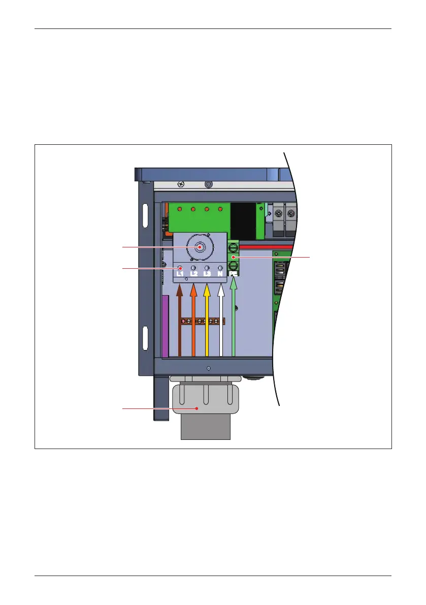
3.3.8 AC Wiring for M80/60U_122 models
Figure 3-23: Location for AC terminal (122 Model)
After inserting
conductor, torque
terminal screw to
49.5 lbf-in (5.6 N•m)
AC switch
NL3L2L1 NL3L2L1
After inserting
conductor, torque
terminal screw to
31 lbf-in (3.5 N•m)
Figure 3-23 illustrates the location of the AC conduit entry and connections to
the 122 model AC terminal block:
- Open all AC switch cage-clamps as noted in Section 3.3.4
- Ensure the correct conductor is connected to the appropriate terminal.
-
After conductor is inserted, tighten L1~N terminal with a torque value of 31 lbf-in
(3.5 N•m), PE terminal with 49.5 lbf-in (5.6 N•m).
EMT
Bottom AC entry
Up to 2 ½ " trade size
conduit (e.g,. EMT)
PEPE
46
Installation
 Loading...


