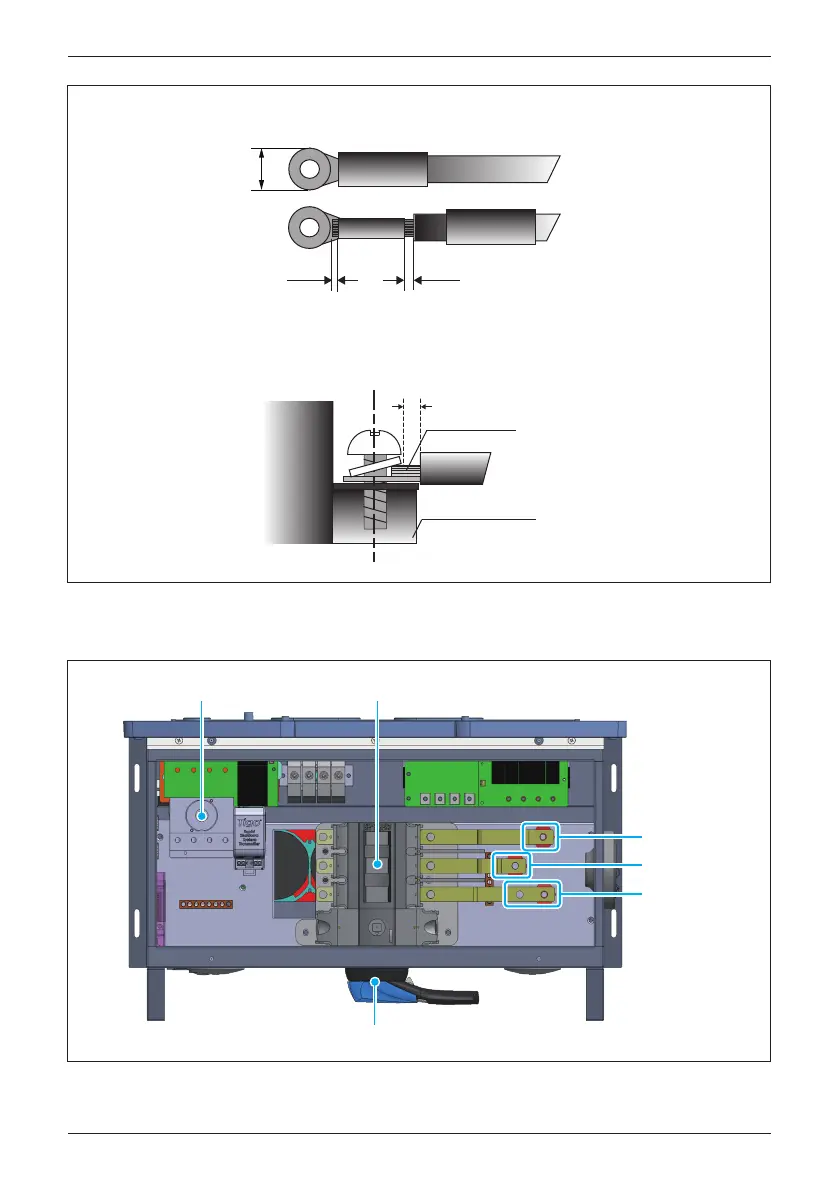
Figure 3-29: Wiring Box layout for M80/60U_121
Figure 3-28: DC terminal lug for M80/60U_121
AC Switch
DC Switch
DC Terminal Block
IN1+
IN2+
IN1
-
& IN2
-
0.5 〜 1mm
<1mm
Conductors
Terminal Block
if> 1mm, it might interfere with screw
・Please follow below instruction for wire crimping.
・To make sure good wire conduction, bare wire should not exceed the edge of
crimping part of lug for more than 1mm.
≤ 25mm
51
Installation
 Loading...


