121
AK5358BET (HDMI : U2101)
AK5358BET Pin Function
ASAHI KASEI [AK4358]
MS0203-J-01 2006/02
- 4 -
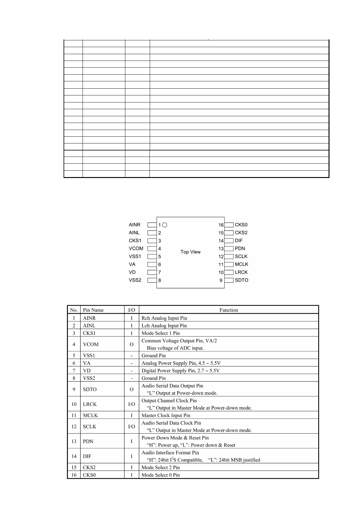
PIN/FUNCTION
No. Pin Name I/O Function
1 LOUT1- O DAC1 Lch Negative Analog Output Pin
2 LOUT1+ O DAC1 Lch Positive Analog Output Pin
3 DZF3 O Zero Input Detect 3 Pin
4 DZF2 O Zero Input Detect 2 Pin
5 DZF1 O Zero Input Detect 1 Pin
6 CAD0 I Chip Address 0 Pin
7 ACKSN I Auto Setting Mode Disable Pin (Pull-down Pin)
“L”: Auto Setting Mode, “H”: Manual Setting Mode
8 PDN I Power-Down Mode Pin
When at “L”, the AK4358 is in the power-down mode and is held in reset.
The AK4358 should always be reset upon power-up.
9 BICK I Audio Serial Data Clock Pin
10 MCLK I Master Clock Input Pin
An external TTL clock should be input on this pin.
11 DVDD -
Digital Power Supply Pin, +4.75∼+5.25V
12 DVSS - Digital Ground Pin
13 SDTI4 I DAC4 Audio Serial Data Input Pin
14 SDTI1 I DAC1 Audio Serial Data Input Pin
15 SDTI2 I DAC2 Audio Serial Data Input Pin
16 SDTI3 I DAC3 Audio Serial Data Input Pin
17 LRCK I L/R Clock Pin
18 I2C I Control Mode Select Pin
“L”: 3-wire Serial, “H”: I
2
C Bus
19 CCLK/SCL I Control Data Clock Pin
I2C = “L”: CCLK (3-wire Serial), I2C = “H”: SCL (I
2
C Bus)
20 CDTI/SDA I/O Control Data Input Pin
I2C = “L”: CDTI (3-wire Serial), I2C = “H”: SDA (I
2
C Bus)
21 CSN/CAD1 I Chip Select Pin
I2C = “L”: CSN (3-wire Serial), I2C = “H”: CAD1 (I
2
C Bus)
22 DCLK I DSD Clock Pin
23 DSDL4 I DAC4 DSD Lch Data Input Pin
24 DSDR4 I DAC4 DSD Rch Data Input Pin
25 DSDL1 I DAC1 DSD Lch Data Input Pin
26 DSDR1 I DAC1 DSD Rch Data Input Pin
27 DSDL2 I DAC2DSD Lch Data Input Pin
28 DSDR2 I DAC2 DSD Rch Data Input Pin
29 DSDL3 I DAC3 DSD Lch Data Input Pin
30 DSDR3 I DAC3 DSD Rch Data Input Pin
31 DIF0 I Audio Data Interface Format 0 Pin
32 ROUT4- O DAC4 Rch Negative Analog Output Pin
33 ROUT4+ O DAC4 Rch Positive Analog Output Pin
34 VREFH I Positive Voltage Reference Input Pin
35 AVDD -
Analog Power Supply Pin, +4.75∼+5.25V
36 AVSS - Analog Ground Pin
37 LOUT4- O DAC4 Lch Negative Analog Output Pin
38 LOUT4+ O DAC4 Lch Positive Analog Output Pin
39 ROUT3- O DAC3 Rch Negative Analog Output Pin
40 ROUT3+ O DAC3 Rch Positive Analog Output Pin
41 LOUT3- O DAC3 Lch Negative Analog Output Pin
42 LOUT3+ O DAC3 Lch Positive Analog Output Pin
43 ROUT2- O DAC2 Rch Negative Analog Output Pin
44 ROUT2+ O DAC2 Rch Positive Analog Output Pin
ASAHI KASEI [AK4358]
MS0203-J-01 2006/02
- 5 -
45 LOUT2- O DAC2 Lch Negative Analog Output Pin
46 LOUT2+ O DAC2 Lch Positive Analog Output Pin
47 ROUT1- O DAC1 Rch Negative Analog Output Pin
48 ROUT1+ O DAC1 Rch Positive Analog Output Pin
Note: All input pins except pull-down pin should not be left floating.
絶対最大定格
(AVSS, DVSS=0V; Note 1)
Parameter Symbol Min Max Units
Power Supplies Analog
Digital
|AVSS-DVSS| (Note 2)
AVDD
DVDD
∆GND
-0.3
-0.3
-
6.0
6.0
0.3
V
V
V
Input Current (any pins except for supplies) IIN -
±10
mA
Digital Input Voltage VIND -0.3 DVDD+0.3 V
Ambient Operating Temperature Ta -40 85
°C
Storage Temperature Tstg -65 150
°C
Note 1. 電圧はすべてグランドピンに対する値です。
Note 2. AVSSとDVSSはアナロググランドに接続して下さい。
注意: この値を超えた条件で使用した場合、デバイスを破壊することがあります。
また通常の動作は保証されません。
推奨動作条件
(AVSS, DVSS=0V; Note 1)
Parameter Symbol Min Typ Max Units
Power Supplies
(Note 3)
Analog
Digital
AVDD
DVDD
4.75
4.75
5.0
5.0
5.25
5.25
V
V
Voltage Reference VREF AVDD-0.5 - AVDD V
Note 3. AVDDとDVDDの立ち上げシーケンスを考える必要はありません。
注意: 本データシートに記載されている条件以外のご使用に関しては、当社では責任負いかねますので十分
ご注意下さい。
 Loading...