31
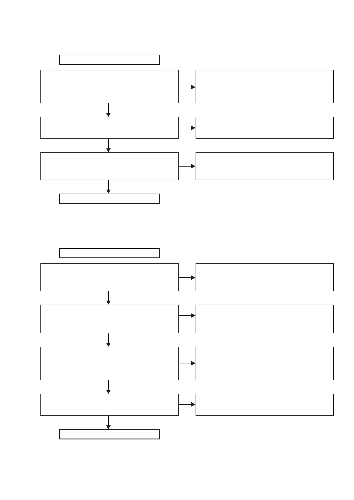
3. Check VMCU
(3.3V standby power)
U9 input voltage check (1pin), spec 12V±10%
Is the voltage in the spec?
U9 output enable check (3pin) H?
U9 output voltage check (5pin), spec 3.3V±5%
Is the voltage in the spec?
1. Soldering check of (U9, R35, C34, C65)
2. After release (R35), conduction check of (C34, C65)
3. Replace (R35→U9)
4. Return to Check "12V"
1. Soldering check of (R52)
2. Replace (R52)
1. Soldering check of (C35, C66)
2. After release (R51), conduction check of (C35, C66)
3. Replace (U9)
NO
NO
NO
YES
YES
YES
Start (MAIN PWB)
Finish
4. Check 3V3
(3.3V system power)
U1 input voltage check (2pin), spec 12V±10%
Is the voltage in the spec?
U1 output enable check (7pin) H?
U1(3pin): PWM waveform do not have a problem?
U1 output voltage check (R3, R5), spec 3.3V±5%
Is the voltage in the spec?
1. Soldering check of (U1, R1, R2, C7, C8)
2. After release (R1, R2), conduct check of (C7, C8)
3. Replace (R1, R2)
1. Soldering check of (U1, R4)
2. Return to check "VMCU", "IPOD_5V", "5V", "1V2", "1V9",
"ADSP_1V1"
1. Soldering check of (U1, C6, L4, R7, R8, C9, C10, C37)
2. After release (R3, R5), conduct check of (C9, C10, C37)
3. Replace (U1→L4)
1. Soldering check of (U1, L4, C6)
2. Replace (C6→U1→L4)
NO
NO
NO
NO
YES
YES
YES
YES
Start (MAIN PWB)
Finish

 Loading...