41
Wiring CTs
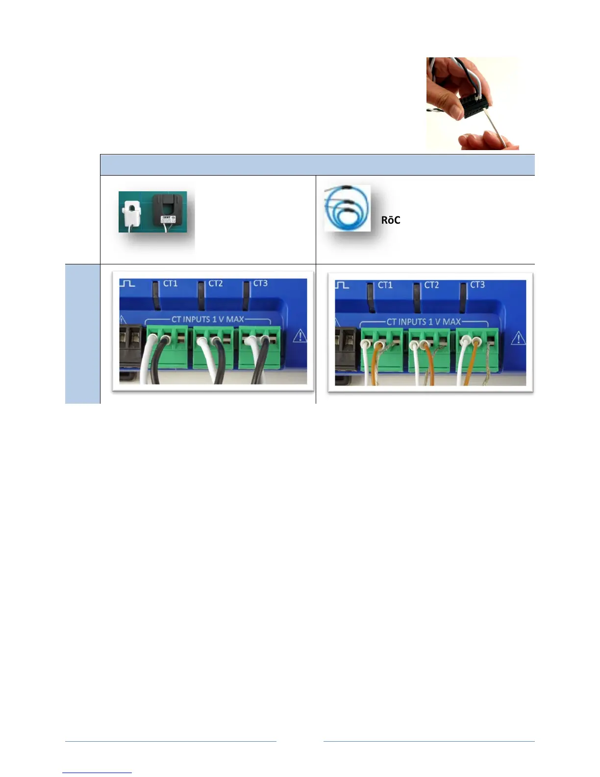
1) Insert the CT wires into the connector/s. See the following CT Type Wiring
Connections table for the correct wiring configuration.
CT Type Wiring Connections
Split-Core *2 wire (+, –) RōCoil *3-wire (+, –, shield)
PowerScout 3037
1) Attach the CTs onto the PowerScout connections labeled CT 1, CT 2 and CT 3.
2) Place the CTs on the phase wires of the load to be monitored and corresponding to the phase of the
voltage leads. The CT labeled CT 1 must be placed on L1 phase voltage wire, CT 2 must be on the L2
voltage and CT 3 on the L3 voltage. Refer to PhaseChek
™
later in this section for information about
the CT LEDs and verifying the CT installation.
www.GlobalTestSupply.com
Find Quality Products Online at: sales@GlobalTestSupply.com
 Loading...