46
POWERING THE METER
Connect the PowerScout meter 14 AWG THHN
Minimum 600VAC rating (or equivalent in order to
maintain 600VAC safety rating of the device) voltage
leads as close as possible to a building-installed,
dedicated circuit disconnect breaker. Mark the breaker
as the “disconnect” for the PowerScout. Refer to the
wiring diagrams for specifics of the wiring connections.
Follow local electrical codes during this installation.
PowerScout meters are self-powered from the L1 and L2
lines. When 80–600VAC or DC is placed across the L1 and
L2 wires, the three phasing LEDs begin to flash in
sequence.
POWERSCOUT SINGLE-PHASE CONNECTIONS
The PowerScout meter can be used to monitor single-phase loads. There are several guidelines to keep
in mind about this type of connection:
1) The PowerScout is powered from a potential between L1 and L2. This can be phase-to-phase (230V)
or phase-to-neutral (115V). With a single-phase 230V panel, the L1 and L2 voltage leads are
connected between the L1 and L2 voltage sources. With a 115V circuit, the L1 voltage lead is
connected to the L1 “hot lead,” and the L2 voltage lead is connected to neutral.
2) Each CT must be paired with the correct voltage source. The current and voltage need to be in-
phase for accurate measurements. For instance, CT 1 would monitor branch circuit supplied by
voltage source L1, and so on.
3) The neutral must be connected because the PowerScout uses line-to-neutral measurements fo
r all
c
alculations.
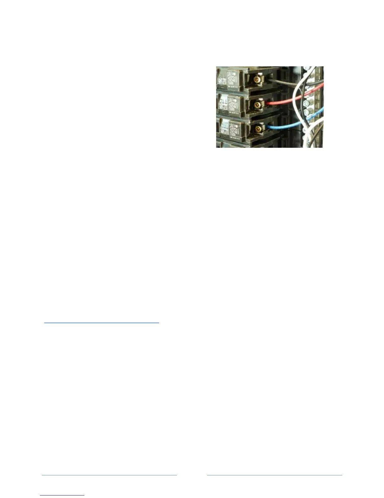
A Typical 230V Single-Phase Panel
Setup (US Wire Colors)
Connect the Black L1 voltage lead to Voltage L1, Red L2 voltage lead to L2 voltage, White Neutral voltage
lead to neutral. CT1 would monitor L1 loads and CT2 would monitor L2 loads. Based on the above
guidelines, CT3 can be used if the Blue L3 voltage lead is connected to either L1 or L2. As long as voltage
lead L3 and CT3 are in-phase, the PowerScout meter will provide correct kW readings. If the Blue L3
voltage lead was connected to L2 voltage source, then CT3 could monitor any L2 branch circuit. Or, if the
Blue L3 voltage lead was connected to L1 voltage source, then CT3 could monitor any L1 branch circuit.
www.GlobalTestSupply.com
Find Quality Products Online at: sales@GlobalTestSupply.com
 Loading...