ConnectCore for i.MX51
©2011DigiInternational,Inc. 111
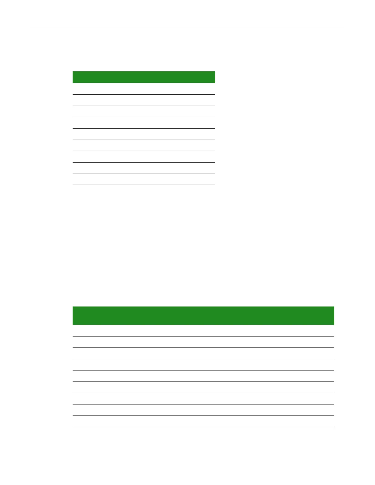
Serial port 2 pins are allocated as shown:
By default, serial port 2 signals are configured as GPIO signals.
Serial Port 1, MEI Interface, X30
The serial (UART) port 1 connector, X30, is a DB-9 male connector. This asynchronous serial
port is operating in DTE mode and requires a null-modem cable to connect to a computer
serial port.
The serial port 1 MEI (multiple electrical interface) interface corresponds to i.MX51 UART
port 1. The line drivers are configured using the switch S6. Refer to the "Switches and Push-
buttons" section of this document for more information.
Serial port 1 pins are allocated as shown:
Pin Function Defaults to
1NC -
2 RXD GPIO1_20
3 TXD GPIO1_21
4NC -
5GND -
6NC -
7RTS# GPIO1_14
8CTS# GPIO1_11
9NC -
Pin RS232
Function
RS232
Default
RS485
Function
RS485
Default
1- - CTS- -
2 RXD GPIO4_28 RX+ GPIO4_28
3 TXD GPIO4_29 TX+ GPIO4_29
4- - RTS- -
5 GND - GND -
6- - RX- -
7 RTS# GPIO4_30 RTS+ GPIO4_30
8 CTS# GPIO4_31 CTS+ GPIO4_31
9- - TX- -

 Loading...


