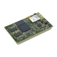
ConnectCore for i.MX51
©2011DigiInternational,Inc. 49
– SD Memory Card Specification Version 2.0: supports High-Capacity SD Memory Cards
– SDIO Card Specification Version 2.0
Supports 1, 4, or 8 bit MMC modes and 1bit or 4 bit SD and SDIO modes
– Card bus clock frequency up to 52 MHz
– Up to 416 Mbps of data transfer for MMC cards in 8-bit mode
– Up to 200 Mbps of data transfer for SD/SDIO cards in 4-bit mode
– Allows cards to interrupt the host in 1-bit and 4-bit SDIO modes, also supports
interrupt period
The following table shows the memory card signals available on the module connectors:
PWM
The ConnectCore for i.MX51 module provides two PWM interfaces. These PWM interfaces
share the output pad in the i.MX51 CPU with the I
2
C bus used on the module for the
accelerometer. In order to use the PWM signals the I
2
C bus must be disabled.
The main features of the PWM interface are the following:
16-bit up-counter with clock source selection
4 × 16 FIFO to minimize interrupt overhead
12-bit prescaler for division of clock
Sound and melody generation
Active high or active low configured output
Can be programmed to be active in low power and debug modes
Interrupts at compare and rollover
Signal Memory
Card 1
Memory
Card 2
Memory
Card 3
Memory
Card 4
Card Detect (CD #) √√
CLK √√√ √
CMD √√√
LCTL √
WP# √√
DATA3 - DATA0 √√√ √
DATA7 - DATA4 √√√

 Loading...