ConnectCore for i.MX51
©2011DigiInternational,Inc. 122
Digi XBee
TM
Module Connectors, X28 and X29
The development board provides two 10-pin, 2.0mm connectors, X28 and X29, supporting a
Digi XBee module.
The XBee serial port is shared with UART port 3 on the development board. Two jumpers (J30
and J31) are used in the development board to select the connector where serial port 3 will
be available. Refer to the “Jumpers” section of this document for more information.
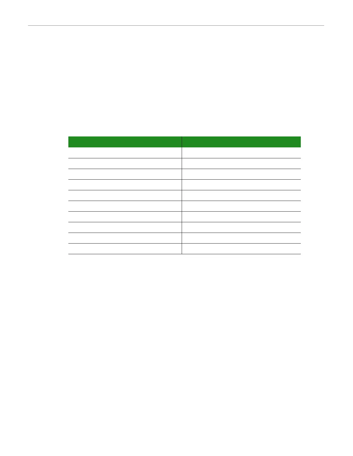
The table below shows the pinout of the XBee module connectors.
Pin Signal Pin Signal
X28-1 +3.3V X29-1 IDENT
X28-2 XBEE_DOUT X29-2
X28-3 XBEE_DIN X29-3
X28-4 NC X29-4
X28-5 XBEE_RESET# X29-5 XBEE_RTS#
X28-6 - X29-6 ASSOC
X28-7 - X29-7
X28-8 - X29-8 ON/SLEEP#
X28-9 XBEE_SLEEP_RQ X29-9 XBEE_CTS#
X28-10 GND X29-10

 Loading...


