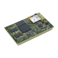
ConnectCore for i.MX51
©2011DigiInternational,Inc. 66
WLAN, LE12
LED indicating WLAN operational status.
Power LEDs, LE3, LE4, LE6 and LE7
All power LEDs are red. The power supplies must be present:
LE3 ON indicates that +9VDC / +30VDC power is present
LE4 ON indicates that battery power is present
LE6 ON indicates that +5VDC power for the development board is present
LE7 ON indicates that +3.3VDC power for the development board is present
User LEDs, LE49 and LE51
The user LEDs are controlled through applications running on the ConnectCore for i.MX51
module. You may use these module signals to implement the LEDs:
Serial Status LEDs
The development board has two sets of serial port LEDs - four for serial port 1 and four for
serial port 2. The LEDs are connected to the TTL side of the RS232 or RS4xx transceivers.
Green means corresponding signal high
Red means corresponding signal low
The intensity and color of the LED will change when the voltage is switching
Signal Name Button GPIO Used
NANDF_RB2/MII_COL/SP12_SCLK/GPIO3_10 LE51 GPIO3_10
NANDF_RB1/PATA_IORDY/SPI2_RDY/GPIO3_9 LE49 GPIO3_9

 Loading...