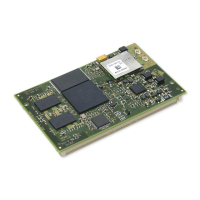
ConnectCore for i.MX51
©2011DigiInternational,Inc. 141
The following table shows the Analog RGB DC parameters.
The following table shows the DC parameter of the ADC subsystem. The ADC subsystem is
used by the touch interface and by the three analog input signals (ADIN).
The following table shows the DC parameter of the digital USB.
The following table shows the DC parameter of the Analog USB.
Tx Differential Output Voltage
10BASE-T
Vout 2.2 2.5 2.8 V
Rx Differential Squelch Threshold
10BASE-T
Vds 300 420 585 mV
Parameter Symbol Min Typ Max Unit
Supply Voltage VDD 2.69 2.75 2.91 V
Parameter Symbol Min Typ Max Unit
Input Voltage range VI 0 - 2.4 V
Input Buffer offset Voff -5 - 5 mV
Conversion Current Iin - 1 - mA
Source Impedance Rin - - 5 k
Ω
Parameter Symbol Min Typ Max Unit
Supply Voltage VDD 2.25 2.5 2.75 V
High-level output voltage Voh VDD-0-.43 - VDD V
Low-level output voltage Vol - - 0.43 V
High-level input voltage VIH 0.7 x VDD - VDD V
Low-level input voltage VIL 0 - 0.3 x VDD V
Current consumption I - - 22 mA
Parameter Symbol Min Typ Max Unit
Supply Voltage VDD 3.0 3.3 3.6 V
Current consumption I - - 6 mA
Parameter Symbol Min Typ Max Unit

