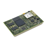
ConnectCore for i.MX51
©2011DigiInternational,Inc. 101
The BE2# signal is connected to the i.MX51 byte enable 2 (D16 - D23).
The BE3# signal is connected to the i.MX51 byte enable 3 (D24 - D31).
The BCLK signal corresponds to the i.MX51 burst clock signal. This clock signal is not
buffered, and its voltage level is +1.8V. This signal is connected to the peripheral connector
through a 0R resister. By default, this resistor is not populated.
The I
2
C interface corresponds to i.MX51 I
2
C port 2. For more information, refer to the I
2
C
chapter in this document.
The signal GPIO3_2 can only be used as an input signal to the i.MX51. This signal is intended
to be used as interrupt line in the peripheral boards.
Downloaded from Elcodis.com electronic components distributor

 Loading...