ConnectCore for i.MX51
©2011DigiInternational,Inc. 74
Digital I/O Connector, X45
The development board provides a 3.81mm green terminal block, X45, for accessing eight on
chip digital GPIOs of the i.MX51 CPU.
On the development board, GPIO3_6 is connected to USER_KEY1. When using this signal as
digital I/O, the USER_KEY1 should not be used.
Note:
The digital I/O interface is not protected against ESD, over voltage or inverse polarity.
Care must be taken when using these signals.
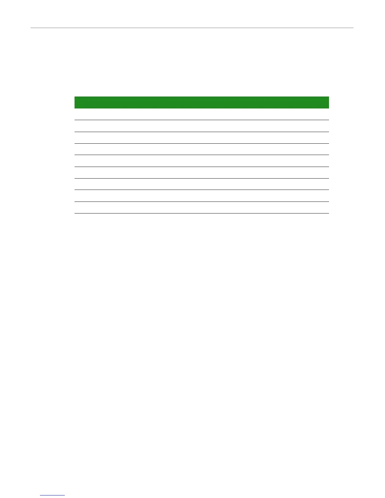
Pin Signal Voltage Level
1 GPIO3_11/SPI2_MISO/NANDF_RB3 +3.15V
2 GPIO3_18/NANDF_CS2# +3.15V
3 GPIO3_9/SPI2_RDY/USER_LED2/NANDF_RB1 +3.15V
4 GPIO3_10/SPI2_SCLK/USER_LED1/NANDF_RB2 +3.15V
5 GPIO3_20/NANDF_CS4# +3.15V
6 GPIO3_21/NANDF_CS5# +3.15V
7 GPIO3_22/NANDF_CS6# +3.15V
8 GPIO3_6/DISPB2_SER_DIO/USER_KEY1 +2.775
9GND 0V
Downloaded from Elcodis.com electronic components distributor

 Loading...


