ConnectCore for i.MX51
©2011DigiInternational,Inc. 93
Module Connectors
See the "Module Pinout" chapter on page 14 for related information.
Signal Rails, J25 and J26
The development board provides two 2x80 pin signal rails, J25 and J26. These connectors
provide most of the signals available on the module connectors and can be used for
measurement or development purposes.
J25 corresponds to module connector J1
J26 corresponds to module connector J2
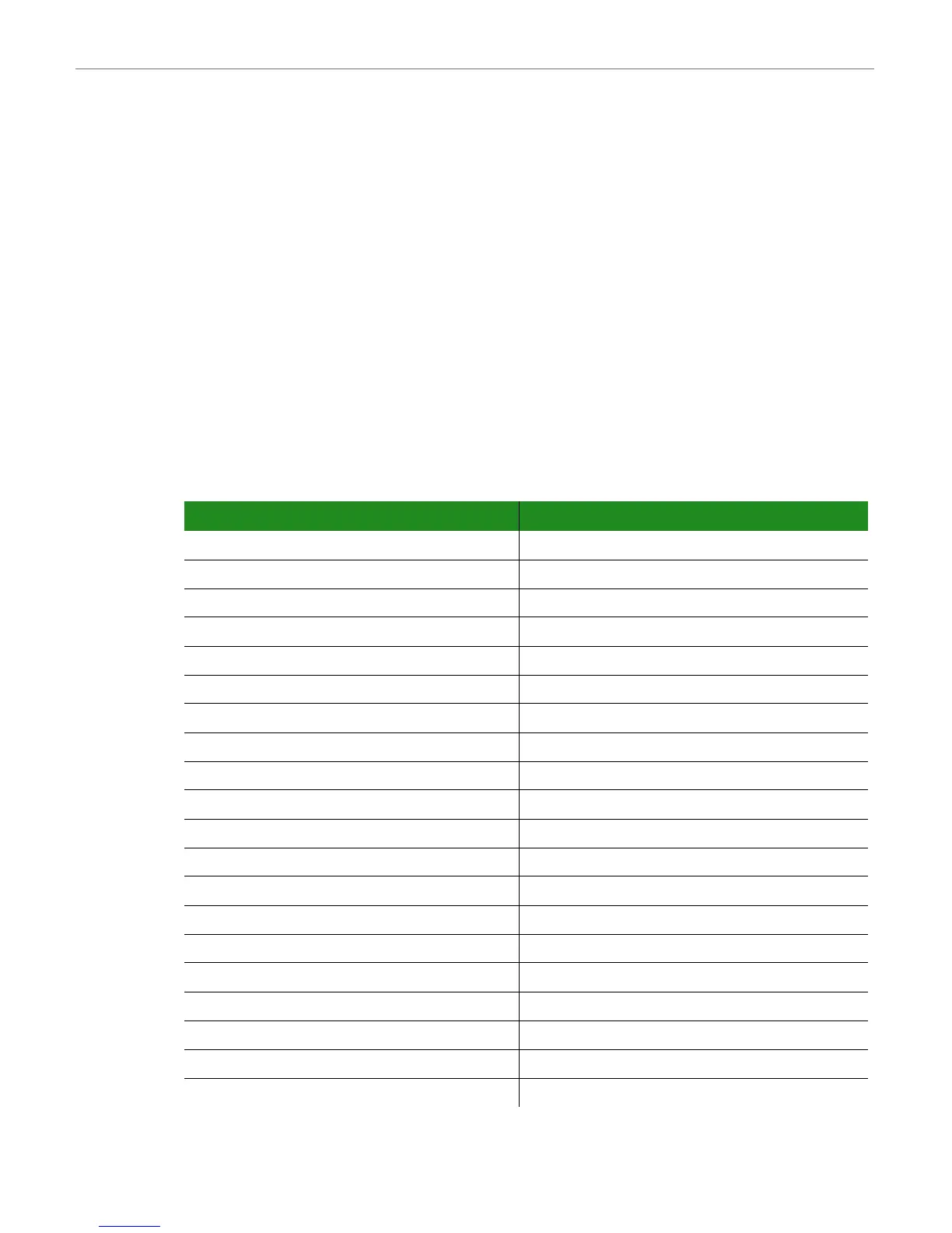
J25 Pinout
Pin Signal Pin Signal
1 CSI1_D8 2 CSI1_D9
3 CSI1_D10 4 CSI1_D11
5 CSI1_D12 6 CSI1_D13
7 CSI1_D14 8 CSI1_D15
9 CSI1_D16 10 CSI1_D17
11 CSI1_D18 12 CSI1_D19
13 CSI1_VSYNC/GPIO3_14 14 CSI1_HSYNC/GPIO3_15
15 CSI1_PIXCLK 16 CSI1_MCLK
17 WLAN_TDO 18 WLAN_TCK
19 WLAN_TDI 20 WLAN_TMS
21 WLAN_LED 22 RS_BT_PRIORITY
23 RS_WLAN_ACTIVE 24 RS_BT_ACTIVE
25 +2.775V 26 WLAN_DISABLE#
27 +2.775V 28 +2.775V
29 MC13892_GPO1 30 +2.775V
31 PMIC_PWRON1 32 PMIC_STDBY_REQ
33 PMIC_INT_REQ 34 PWRGTDRV1
35 CHRGLED 36 PWRGTDRV2
37 CHRGSE1# 38 VCC_COINCELL
39 VLIO 40 +5V_IN
Downloaded from Elcodis.com electronic components distributor

 Loading...


