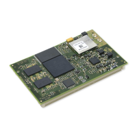
ConnectCore for i.MX51
©2011DigiInternational,Inc. 76
Ethernet 1, RJ-45 Connector X7
The table below shows the pinout of the Ethernet 1 RJ-45 connector.
The table below shows the description of the Ethernet 1 LEDs.
Pin Signal 802.3af End-Span
(mode A)
802.3ad Mid-Span
(mode B)
Description
1 TXD+ Negative V
Port
Transmit data+
2 TXD- Negative V
Port
Trandmit data-
3 RXD+ Positive V
Port
Receive data+
4 EPWR+ Positive V
Port
Power from switch+
5 EPWR+ Positive V
Port
Power from switch+
6 RXD- Positive V
Port
Receive data-
7EPWR- Negative V
Port
Power from switch-
8EPWR- Negative V
portP
Power from switch-
LED Description
Yellow Network activity (speed):
- Flashing - indicates network traffic
- Off - no network traffic
Green Network link:
- On - indicates an active network link
- Off - no network link present
Downloaded from Elcodis.com electronic components distributor

 Loading...