SYSTEM OVERVIEW
77091 Issue 2 November 2003 13
valve is fitted in order to depressurise an empty ink bottle when changing to a fresh
supply.
Due to the air pump, there is a constant pressure of ink driven up the coiled
supply tube linking the base unit to the print head (a second, separate coiled tube
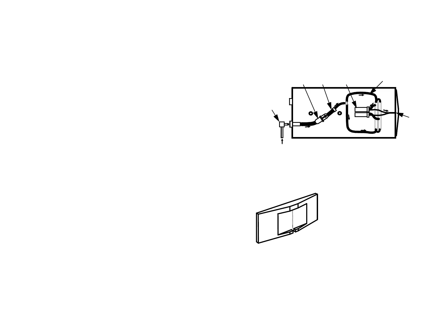
provides the print head with power). A quick disconnect “QD” plug at the end of
the ink supply tube is fastened into the rear of the print head.
Entering the print head, the ink passes through a 25 micron ink filter which traps
any minute particles suspended in it, then an ink reducer. Finally it is distributed
to all the inlets in the solenoid valve array. The diagram above shows the ink path
in a typical print head. For clarity, only two of the valves are shown. The number
of valves and layout of the ink distribution assembly depends on the model used.
On activation, each solenoid valve allows a
measured amount of ink (still under air pump
pressure) to move forward into the outlet tube
linking the valve with the nozzle plate. The
nozzle plate consists of a series of openings
arranged vertically. The ink is ejected from
these openings in droplets, driven a few
millimetres onto the surface of whatever is to be
printed. Each time the valve is activated more
ink is released into the relevant outlet tube,
forcing another droplet of ink out of the nozzle
plate.
ValvesReducer
Ink Distribution
Assembly
QD Ink
Connector
Ink Filter
Nozzl
Plate
Print Head Ink Distribution
Printer Nozzle Plate
 Loading...