INSTALLATION
32 77091 Issue 2 November 2003
Avoid locations where operators or machinery moving close to the printer are
likely to trigger the photocell. Do not place the printer opposite a large reflective
area as this may also trigger the photocell. When printing on both sides of
product, never place the two printers exactly opposite - the photocells will trigger
each other.
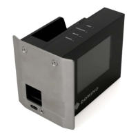
Buffer plate
Each printer incorporates a buffer plate to
afford some protection to the nozzle plate, to
provide a degree of print-head-to-product
spacing for correct character generation and
to help prevent smearing before the ink
dries. In the C16, this is built into the nozzle
plate itself.
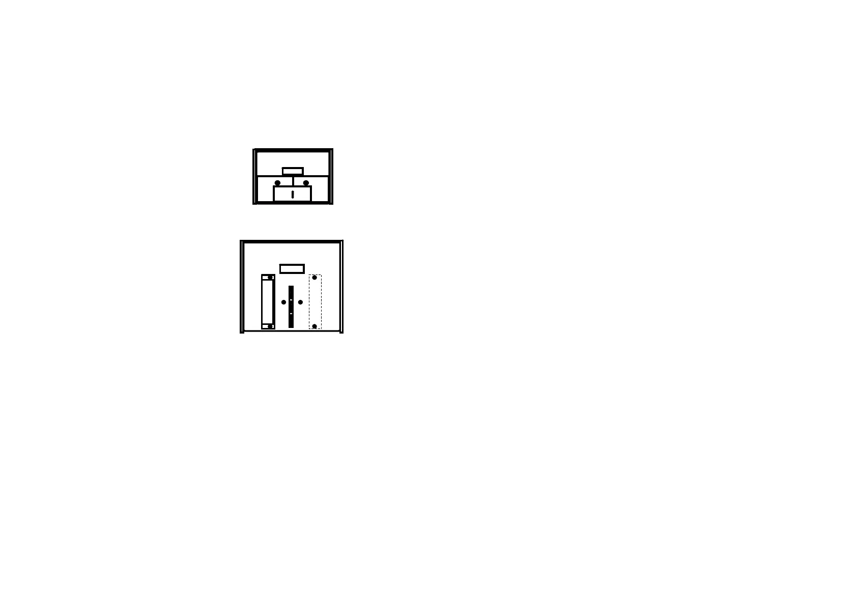
In all other models, the buffer plate is
separate to the nozzle plate and is bolted in
place. The position of the buffer plate may
need to be changed to correspond with the
direction of product movement on the
conveyor - make sure that the product
reaches the buffer plate before it reaches the
nozzle plate. This involves removing the
print head cover, which is explained in the
MAINTENANCE chapter of this manual.
Mounting the printer
The exploded diagram (below) shows the arrangement of components used in the
mounting of a printer with a one litre base. Items A and B are not required when
installing a three litre base as they are built into the base unit.
Combined Buffer and
Nozzle Plate
Separate Buffer Plate
- Position as Required
 Loading...