8
System Layout
2.2 Rear Panel Layout for 2U models
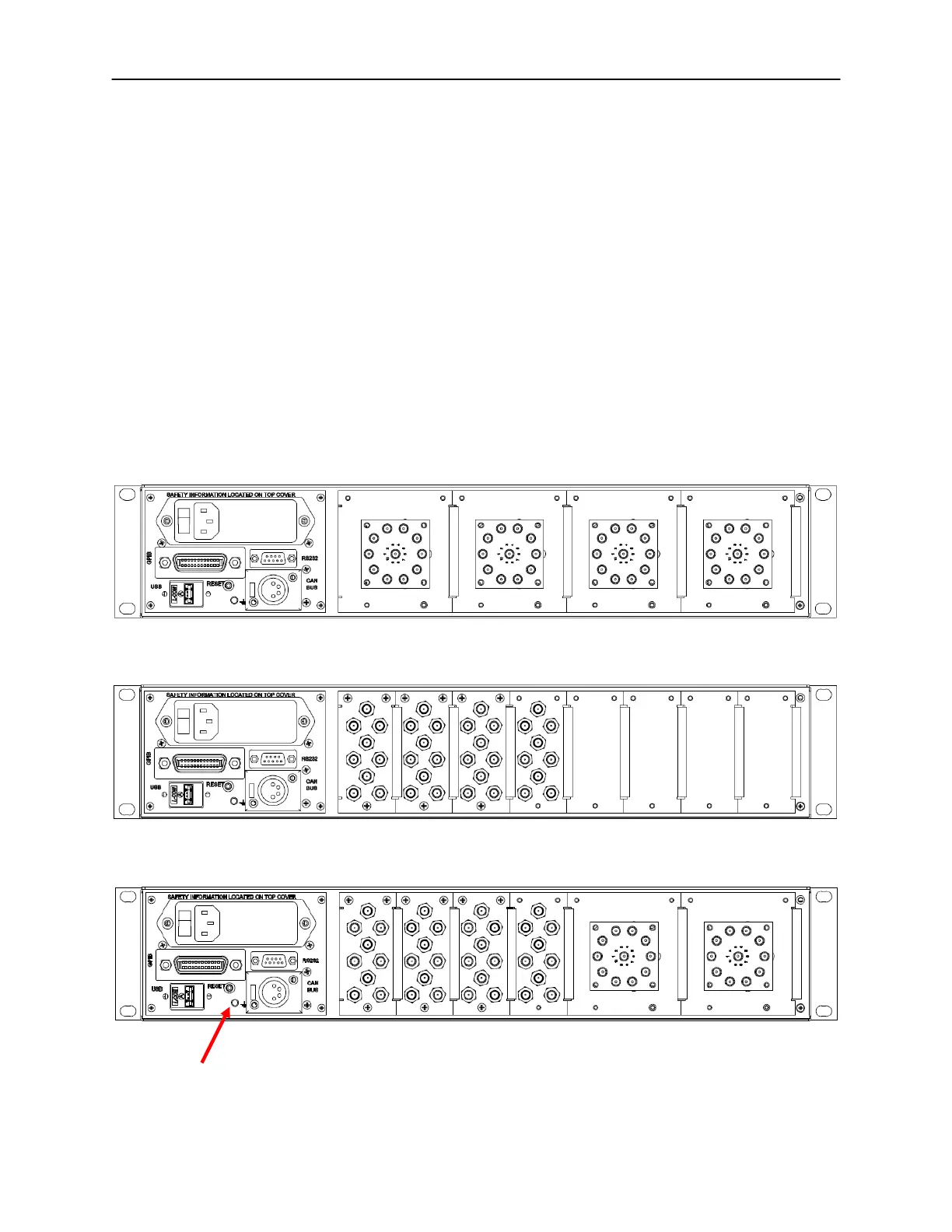
Figure 2-2 shows the general layout of the rear panel of a variety of 2U models.
All models have common parts which include:
• Power Entry Module with built in Fuse
• Chassis Ground Post
• 9-Pin D-Sub Female RS232 Connector
• 4-Pin XLR Female CAN Bus Connector
• GPIB (IEEE 488) 25 pin Centronics Connector
• USB type A Connector
Other parts that are not common to all models are Coaxial RF switches and/or
RF connectors.
2U MS series (with external switches)
2U MS series (with internal switches) or MP series or CB series
2U MS series combined with MP series or CB series
GND stud
Figure 2-2, Various 2U Models Rear Panel Layout
 Loading...