18
Connections
3.4 CAN Bus Connection
This connection allows the internal matrix controller to be easily interfaced to
another Dow-Key Microwave Switch Matrix, using a one-to-one (straight
through) cable. This allows a master matrix to control an extension matrix.
However, the extension matrix being interfaced must not have any internal,
intelligent controller; it must be a simple RF Switch Matrix extension.
Furthermore, the switches in the extension matrix being interfaced must have
CAN ID’s unique to any others connected to the internal master matrix
controller. See Section 4 for more information.
Care must also be taken to limit the internal power supply’s current draw on the
+12 VDC to a maximum of 7 Amps. Note that this includes all switches of the
master matrix and the extension matrix combined.
If the total current draw is below 7A, the extension matrix’s switches will be
powered by the master matrix (thru pins 1 and 4).
In cases where the total current exceeds 7A, the extension matrix needs to
have its own internal power supply. In these cases, the interconnection cable
shall only use pins 2 and 3 for the CAN bus communication.
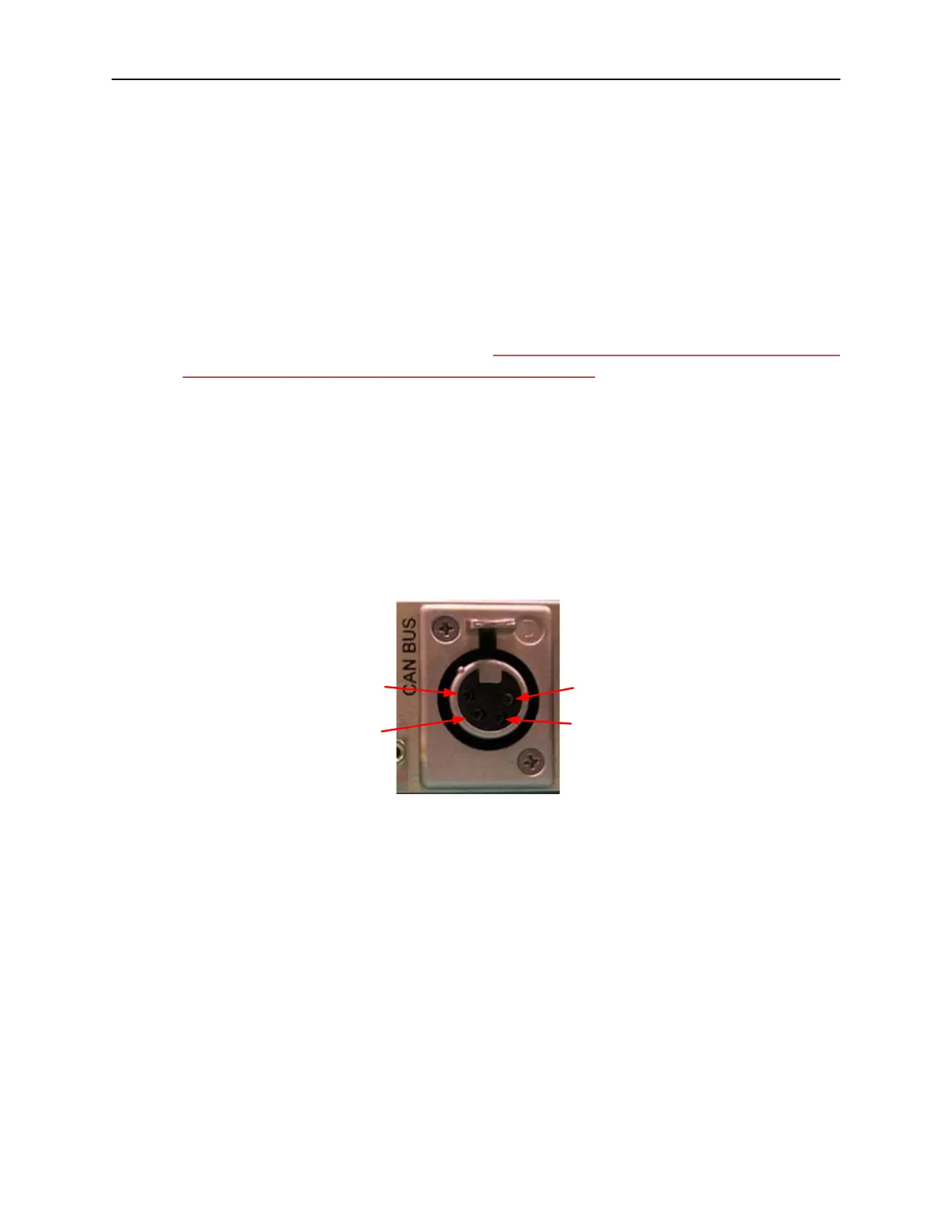
Figure 3-3 and Table 3-3 show the pin numbers and functions for the CAN Bus
connector.
1
2
3
4
Figure 3-3, CAN Bus Connector Pin Numbers
The mating connector is Deltron 701-0400. The pin outs (embossed on connector faces)
are:
1. +12 VDC, 7A max (this current is for master and extension matrices combined. See
Individual switch data sheets for current draw).
2. CAN LO
3. CAN HI
4. +12 VDC Return (GND)
Table 3-3, CAN Bus Connector Pin Functions
 Loading...