Field Description
Dispenser (POS system
settings)
This field identifies the index of the first pump (refer to the Gilbarco BCD Dispenser Interface
Protocol).
Select Index 0 if the first pump in the POS/FCC is identified as Pump 0.
Select Index 1 if the first pump in the POS/FCC is identified as Pump 1.
The word “Pump” refers to the Fueling Position as shown in the Gilbarco BCD Dispenser
Interface Protocol.
Nozzle (POS system
settings)
This field identifies the index of the first nozzle of the pump (refer to the Gilbarco BCD Dispenser
Interface Protocol).
Select Index 0 if the first nozzle in the POS/FCC is identified as Nozzle 0.
Select Index 1 if the first nozzle in the POS/FCC is identified as Nozzle 1.
The word “Nozzle” refers to the Meter Identifier as shown in the Gilbarco BCD Dispenser
Interface Protocol.
Total dispensers
Identifies the total number of pumps (Fueling Positions) that are connected to the tanks
monitored by the console
Max nozzles Identifies the maximum number of nozzles for each pump.
Click Save when you complete the top section of the Site mapping tab configuration.
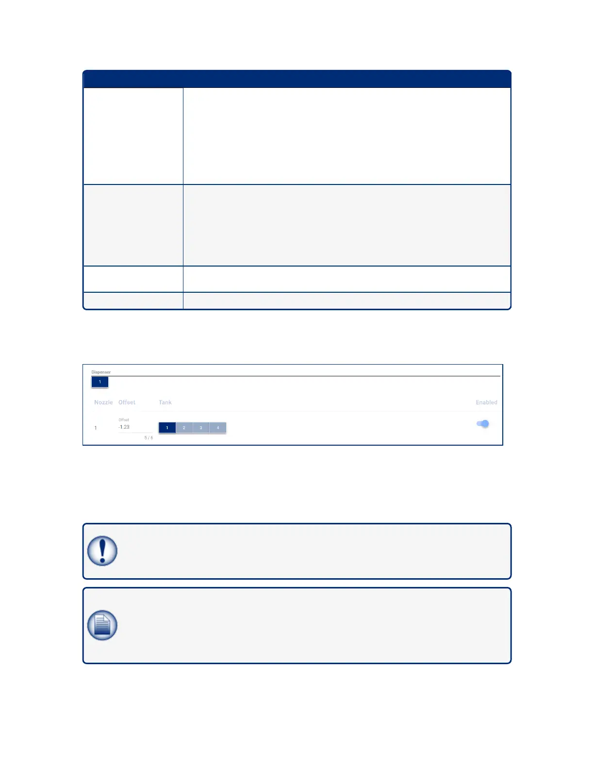
6.1.8.1 Map Dispensers and Nozzles to Tanks
1. Select a Dispenser.
2. Map each Nozzle to a Tank.
3. The offset is the "meter drift" value of the dispenser (the meter drift is set during a pump calibration).
4. Use the swipe button to Enable the Nozzle to Tank mapping.
IMPORTANT: Nozzle-to-tank mapping must be done correctly or the console will
communicate incorrect sales data for the tanks and the autocalibration / reconciliation function
will not operate correctly.
NOTE: When manifolded tanks are in use, the first tank in the Manifold Group should be
mapped to the related nozzles. The reconciliation reports and the delivery reports for the full
manifold Group will be shown under the 1st tank.
Autocalibration cannot be performed in a tank that is part of a Manifold Group.
M2051-EU Rev.: 1 Dover Fueling Solutions
Page 27
 Loading...
