63
TESTS & ALIGNMENTS
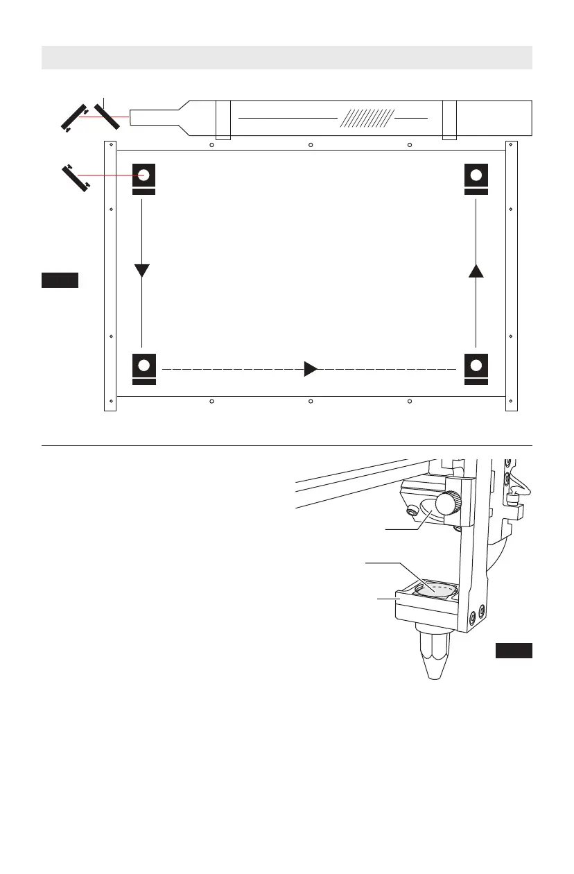
4 Corner Mirror Alignment Test
Before running the first job, check to
make sure that the mirrors are properly
aligned. This test should also be
performed as a troubleshooting measure
for power loss, clipping, or incomplete
cutting. For this alignment test the laser
must be “test fired” once in each corner
of the machine. This is done to make sure
the laser beam is following the correct
path to the mirrors, to the focus head,
and ultimately through the lens to the
material. Figure 32, Mirror Alignment
Layout.
Note: Laser lid must be closed for each
test fire.
Materials needed:
• Thermal paper (supplied).
• 2.5mm hex wrench (supplied).
1. Open the lid.
2. Place the thermal paper: Take a small
piece of thermal paper approximately
the same size as the face of the lens
and place it over the focus lens under
Mirror #3. See figure 33.
3. Press the paper down with a finger so
that a circle appears that
demonstrates the outer rim of the
lens. Sometimes pencil lead or crayon
will help to show the edges of the lens
and mirrors.
Test Fire
Test Fire
Test Fire
Test Fire
A
BC
D
Mirror 1
M
irror 2
Laser Head
Mirror 3
Axis A-B
Axis B-C
A
xis C-D
Beam Combiner
L
ens
Focus Lens
Mirror 3
Fig. 33
Fig. 32
Mirror
Alignment
Layout
Thermal
Paper
 Loading...