b.
The communicator’s red and yellow LEDs flash together while it initializes. The red and yellow LEDs will continue
to flash until the communicator has successfully communicated to all programmed receivers.
NOTE: During radio reset, the two green LEDswill flash alternately.
NOTE: Initialization may take several minutes to complete. Do not continue to next step until the red and yellow LEDs have
stopped flashing. (If only the yellow LED is flashing, there is a communicator trouble and the green LEDs are not
valid for communicator placement test). Correct trouble indicated by flashes on yellow LED before continuing. See
Table 8 for troubleshooting assistance.
7.
Perform the communicator placement test below.
8.
Mount the panel in final location indicated by placement test.
Communicator Placement Test
Cellular Communicator Models Only
To confirm that the cellular antenna location is suitable for radio operation, perform the placement test as follows:
NOTE: It might be necessary to relocate the panel or install an optional extension antenna during this procedure, if the
radio signal strength is too low.
1.
Confirm that the yellow LED on the communicator is not flashing. A flashing yellow LED indicates trouble on the com-
municator. See Table 8 to troubleshoot and correct the cause of this trouble before continuing to the next step.
2.
Confirm that the strength of the radio signal on the yellow LED and the 2 green LEDs on the communicator meet or
exceed the minimum signal level requirement. Minimum signal level: The yellow LED is OFF and the green LED 1
(furthest from the yellow LED) is ON (not flashing) for the panel location to be acceptable. For interpretation of
receiver strength on LEDs, refer to the table “Radio Signal Strength”.
Cellular Signal Strength Display - LCD Keypad only
The cellular network signal strength can be checked on the keypad LCD screen by entering installer programming section
[850]. The LCD will indicate the SIM card activation status followed by up to five bars of signal strength. This display will auto-
matically update every three seconds. For the relationship between signal strength bars, CSQ level, and signal level in
dBm, refer to “Radio Signal Strength”.
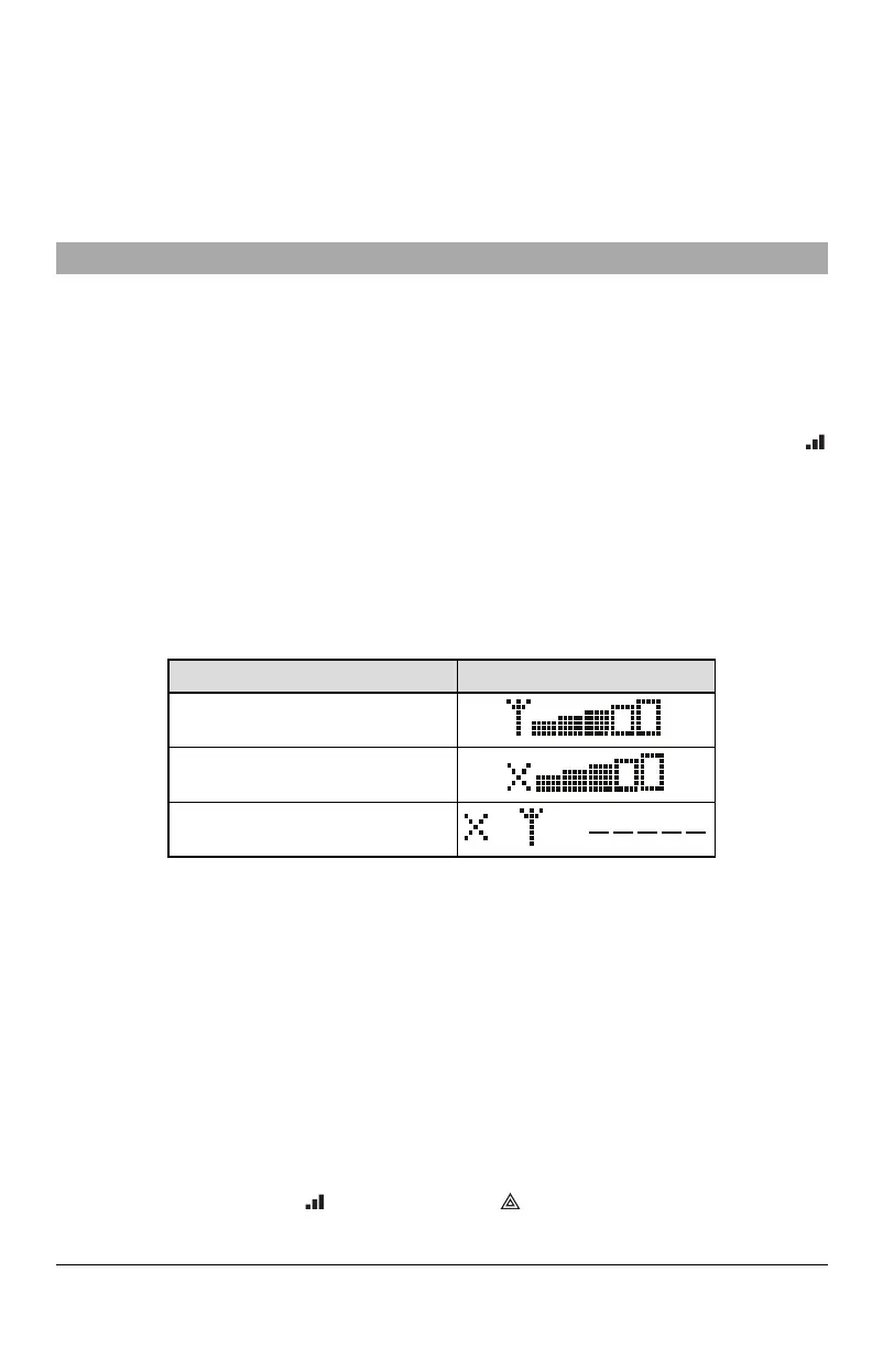
Table 4: Signal Strength Display
Description Display
SIM card active and current signal strength
SIM card inactive and current signal strength
Radio not registered
NOTE: If the required signal strength is too low with the panel in its current location, the panel must be relocated or an
external antenna is required.
If required, the following cellular extension antenna kits are available to the installer:
l GS-15ANTQ - 4.57m (15’) internal antenna extension kit (suitable for interior mounting).
l GS-25ANTQ - 7.62m (25’) external antenna extension kit (suitable for interior/exterior mounting).
l GS-50ANTQ - 15.24m(50’) external antenna extension kit (suitable for interior/exterior mounting).
Specific instructions for the installation of the extension antenna are included with the kit. Observe all the electrical safety
instructions regarding the installation of the antenna. All the wiring of the equipment shall be fully compliant with the local
rules and regulations.
3.
If required, install the antenna extension and perform the following steps to determine the best location for placement
of the antenna:
a.
Disconnect the white whip antenna from the panel.
b.
Attach one end of the antenna extension cable to the threaded antenna connector on the panel and the other
end to the external antenna.
4.
Move the extension antenna to various locations while observing the two green LEDs on the panel.
a. Continue to reposition the extension antenna until it receives an acceptable (minimum one green LED ON solid)
signal strength.
NOTE: Minimum strength is: green LED 1 flashing and yellow LED off. If green LED 1 is flashing, relo-
cation should be considered.
14

 Loading...