40 8-10 kVA, 50/60 Hz (1-phase input) &
8-15 kVA, 50/60 Hz (3-phase input)
P-164000341
User's Guide Revision 1
7 Software and connectivity
The software Suite CD-ROM that is bundled with the UPS contains software distributions and
documentation in CD format. Furthermore, the comprehensive connectivity option portfolio includes
Web/SNMP adapters for networked environments, Modem card for 24/7 remote monitoring,
ModBus/Jbus card for building management system integration, relay interface cards for industrial
and facilities use and RS-232 cards for serial communication to one or multiple computers.
7.1 Communication cables
It is recommended that the control cables and power cables be installed on separate trays. Where
control cables will cross power cables make sure they are arranged at an angle as near to 90 degrees
as possible.
All control cables shall preferably be shielded. If the shield is grounded, this shall take place on only
one end of the cable.
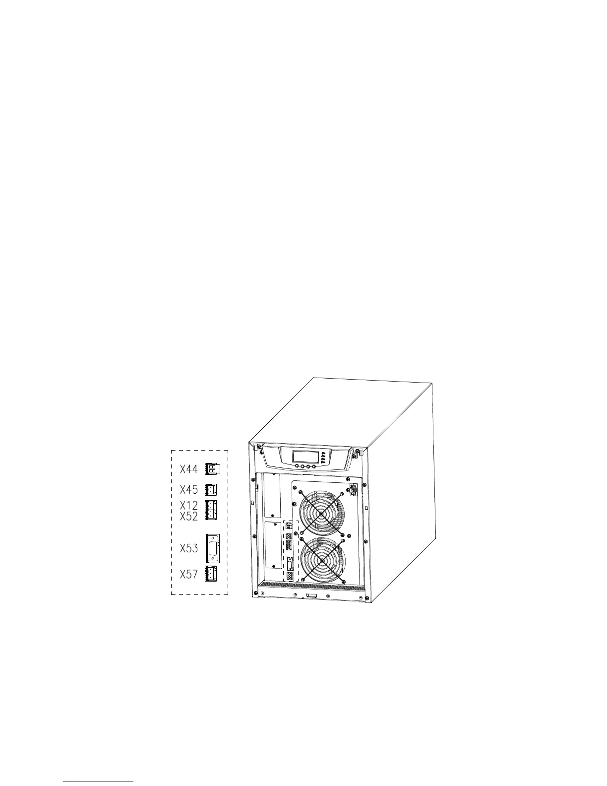
The procedure for connecting the control cables is the following:
1. Remove the front cover by lifting the cover from the bottom outwards by releasing the
retaining clip. It’s located in the bottom part of the bezel.
2. Locate the control terminal or XSlot module where you want to install the communications
cable.
Figure 7-1: Location of control cable terminals: Signal inputs (X44 & X45); EPO (NC (X12)
& NO (X52)); RS-232 (X53); Relay output (X57)
 Loading...